Guys, and Gals:
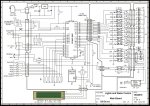
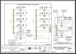
I'll start with a little background. I am aiming to control a servo valve to control the watering of my garden. I have done a search on the forum and read what is available. At this point I haven't picked a chip yet although I believe I am right in saying that the pic chips will sink or source 20 milliamps per pin with a maximum of 90 milliamps per chip. This would also be at 5 volts. I bought an Orbit servo valve that has an inrush current rating of .4 amps and a holding current of .2 amps. I also found an Opto 22 OAC5 Standard AC Output Modules that I had sitting around. I downloaded the data sheet on it and I guess that is where my questions start. The line voltage, operating voltage range, and current rating all are within the parameters I will be using. The logic voltage is 5 VDC Nominal. The logic voltage range is 2.5 to 8 volts so that should be within my range also.The logic picup voltage is 2.5 volts and the dropout voltage is 1 volt DC The logic input current is 12 milliamps. Am I right to state that I can drive this directly from a pic chip? The logic input current is 12 milliamps so that should be under the max 20 milliamps for the chip, and the voltage is within the chips range. Having said this I am assuming I really should use a transistor to drive it just to provide a little isolation to the pic chip. Also, if I want to drive a bunch of these from one chip I would need to drive transistors to keep me from running above the 90 milliamps per chip. I am powering the orbit with a 24 volt AC wall wart that I bought from Radio Shack. Does this sound like I am on the right track? Right now I am working on controling the valve. I'll work on the sensor after I get this figured out. Any thoughts, corrections, or ideas are welcome. Tks.
I'll start with a little background. I am aiming to control a servo valve to control the watering of my garden. I have done a search on the forum and read what is available. At this point I haven't picked a chip yet although I believe I am right in saying that the pic chips will sink or source 20 milliamps per pin with a maximum of 90 milliamps per chip. This would also be at 5 volts. I bought an Orbit servo valve that has an inrush current rating of .4 amps and a holding current of .2 amps. I also found an Opto 22 OAC5 Standard AC Output Modules that I had sitting around. I downloaded the data sheet on it and I guess that is where my questions start. The line voltage, operating voltage range, and current rating all are within the parameters I will be using. The logic voltage is 5 VDC Nominal. The logic voltage range is 2.5 to 8 volts so that should be within my range also.The logic picup voltage is 2.5 volts and the dropout voltage is 1 volt DC The logic input current is 12 milliamps. Am I right to state that I can drive this directly from a pic chip? The logic input current is 12 milliamps so that should be under the max 20 milliamps for the chip, and the voltage is within the chips range. Having said this I am assuming I really should use a transistor to drive it just to provide a little isolation to the pic chip. Also, if I want to drive a bunch of these from one chip I would need to drive transistors to keep me from running above the 90 milliamps per chip. I am powering the orbit with a 24 volt AC wall wart that I bought from Radio Shack. Does this sound like I am on the right track? Right now I am working on controling the valve. I'll work on the sensor after I get this figured out. Any thoughts, corrections, or ideas are welcome. Tks.
Last edited by a moderator:
 eclectic was asking about the datasheet for the "Orbit servo valve"