PWM vs. ADC

Vmax

Member
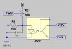
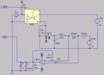
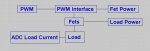
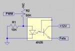
I’m using a PICAXE 28X1 and reading ADC current thru a load. I’m also using PWM to vary current thru the load (see att 1). The PIC reads current using a 0.05 ohm shunt going to an op-amp (gain 10). I think I’m getting some kind of interference between PWM and ADC reading. The PWM interface is in att 2. When I disconnect fet power, load power and op-amp power, I get the following ADC readings for current (should be 0):

duty=49 current=1
duty=49 current=1

duty=49 current=4

duty=49 current=1
duty=49 current=0
duty=49 current=5
duty=49 current=1

duty=49 current=1
duty=49 current=13
duty=49 current=1

duty=49 current=1
duty=49 current=1
duty=49 current=21
duty=49 current=1
duty=49 current=1

duty=49 current=1
duty=49 current=0
duty=49 current=6
duty=49 current=1

duty=49 current=1
duty=49 current=1
duty=49 current=13
duty=49 current=1

duty=49 current=1
duty=49 current=1
duty=49 current=20
duty=49 current=1

I’m getting nasty spicks. When I disconnect the PWM pin, I consistently get:

duty=49 current=1

Stumped. :confused: Any ideas?
 

Attachments

BCJKiwi

Senior Member
Can you post the whole circuit - a sketch would do - can't quite figure out all the factors from your description.

Thanks
 

Dippy

Moderator
I'll second that. Not enough info.

We can't see how you measure your current and if you don't use a low-pass type filter arrangement to your current sensing amp then it may return transient values.

In a circuit I am doing where I am sensing current from a Switched Mode circuit, where there are a lot of spikes, I have to RC the current sensor AND do an ADC average to reduce the spiky effects. You may even have to LCR the inputs to attenuate of spikes.
It may even be related to your circuit layout or track dimensions on a pcb.. who knows...? And have you got a cap or two on your PICAXE power pins?
Is your current sense on the supply high-side or ground return low-side?
How good is the power supply to the PICAXE? Decoupling?
 

tiscando

Senior Member
pulse width modulation

Were you thinking that pwm is simply a steady voltage? PWM (Pulse Width Modulation) is actually timed electrical pulses and when you change the duty, you are varying the witdh or the 'on' time of the pulse, not changing a voltage.
So that's why you are getting those 'nasty spics', so to convert PWM into a steady voltage, connect a 10uf capacitor (higher capacity is better) where the 10k resistor (R1) connects to in your diagram
You don't need this capacitor when just varying the speed of a motor, or the brightness of a lamp/LED, because the pwm pulses (cycles) at a very high speed (above 10kHz), which means that the LED/lamp won't flicker.:)
 

Attachments

Last edited:

Vmax

Member
D'oh! I was hopping you guys wouldn’t ask for a detailed circuit. Aren’t your mind reading abilities up to snuff? :D I’ll need to work on that one for a bit.

From what I get so far, it does seem possible that the PWM is interfering with ADC. What gets me is that there is still interference even when there’s no power to the FETs, load, or op-amp. I’m guessing the problem could be were the PWM circuit goes back to ground. Maybe a cap could help?

“I’ll be back.”
 

Vmax

Member
I'm back. I have a basic pic of my circuit. Hope it's not too confusing. I drive the PICAXE with a 7805 from a wall wart (9V 500mA), with separate power sources for the FET (16V), load (12V), and op-amp (+5V -5V). The circuit is in two sections. Everything connected to the right of the opto is on a separate board about 2 feet away for other components.
 

Attachments

BCJKiwi

Senior Member
Presumably everything below the FET -V rail is also on the same board as the PICAXE - please confirm.

As the PICAXE is using a different supply from the OP-Amp, is the 0V of the opto-isolator and op-amp common to the 0V of the PICAXE - Please confirm.

The whole circuit is always helpful.
 

Dippy

Moderator
Blimey, that's complicated.

So your power to PICAXE is completely isolated from all this lot is it?
What is the ADC like if you pull out the 741?
Don't cut'n'paste a long list, just a one sentence will be fine.

And be aware of reactive effects from that inductor nipping off to your current sensor.
 

Vmax

Member
Hi Dippy and BCJKiwi

I didn’t mean to make it look complicated. I’ve attached a revised circuit. Everything in the box is NOT on the same board as the PICAXE and is a few feet away. One of the things I’m trying to look at is the effect of the power components (L1 and C1) on the PWM signal going into the load.

The 0V op-amp power supply is common to the -V rail of the PICAXE, and so is the opto. I haven’t tried the ADC without the op-amp, but the voltage drop across the shunt is around 2mV, so I don’t think the ADC would read much.

I’m still testing things out and getting familiar with these components, but I don’t plan on having different power sources in the final circuit (if I get there :eek:).
 

Attachments

BCJKiwi

Senior Member
I doubt there is very much wrong at all.

Assuming the readadc is readadc10 (no program posted so we're just guessing), with power off everything else, readadc10 is seeing stray stuff being picked up on the 'aerial' of all the attached wiring out to the op-amp.

The highest reading reported is 30. 30/1023 = 0.029 V out of the (presumably 5V supply) or 0.58 % - not much for a floating input! Most of the readings are way less - 6/1023 is only 0.0059V or 0.1% of supply.

What happens if you lift the wires off the shunt and connect a single dry cell and voltage divider (or a bench supply) with < 0.5V in place of the shunt, and, power up the op-amp? There should be a reading on ADC that relates to 10X the voltage applied.

Is this stable?
 

Dippy

Moderator
The reason I suggested running it without the 741 (and the rest of the circuit unpowered) was that then all the ADC input would see would be a line mostly grounded by a 10K res.

Now you've said there is a load of wire kicking about I'll go along with BCJ unless you have made a wiring mistake.

Is that op-amp circuit for current sensing OK there? Normally you have a differential setup for good linearity when using high-sided current sensing. If it is OK then fine.

2mV on load? on a 0R05 shunt. Are you sure? Thats not a lot of current. I reckon you'll have problems with reactive spikes upsetting your current sensing. If so little current why do you have such a FAT FET? A fat MOSFET has quite a gate capacitance. I dunno how fast you intend to PWM it but your circuit is pretty wimpy for efficient driving.

Having said that, your slow driving may be saving you. Fast driving of the MOSFET and depending on the load R could produce quite high voltages across your MOSFET and C1. But as it seems slow and your current is low then you'll probably be safe.
Suggest you have a little read-up about Inductors and associated equations about energy stored etc.
 
Top