PWM question - forward and reverse?

Denzel

Senior Member
I am trying to control a motor (forward and reverse) using an L293D but its going too fast for my application (knitting machine.... yes, i said knitting).
Im using the 14m so there is only one PWM pin I can use.
Im still trying to get my head around HPWM and I came across this post...

http://letsmakerobots.com/node/2525

Code:
The picaxe manual refers to the " hpwm motor driver datasheet" but the only reference I found was
on the picaxe forum archive where someone said the datasheet was being written. That was one
year ago. I gave up on HPWM and stuck with pwmout

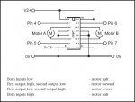
You can use speed control in two directions with the pwmout command. Remember that 75% in
terms of pwm means the pwm pin is low 25% of the cycle and highthe other 75%

I connected output pin 1 and PWM1 (=input pin 1) to the motor driver for the motor A.

To move forward at 75% speed. make output 1 low and use pwm 1 with 75% of the cycle high.

To reverse at 75% speed. make output 1 high and use pwm 1 with 25% of the cycle high. 

That way you only need 1 PWM signal per motorfor bi-directional speed control
Is this possible? note that hes using output 1 and input 1, two different pins (confused me at first)
 

jodicalhon

New Member
Yes, that should work, Denzel.

With one side of the motor held low, and the other side PWM'd at 75%, the motor will turn one way at 75% speed.

Holding the same side of the motor high, and PWMing the other side at 25%, the motor will turn the other way at 75% speed.
 

Denzel

Senior Member
...

Thanks
Im testing it out now, im onto my last L293D so I thought id be safe to double check

denz
 

Denzel

Senior Member
...

Here is the final code I used to achieve this. using an 08m or 14m I have used a single pwm (pin2) to control forwards and reverse,
I used the pwm command as apposed to pwmout as this did not seem to work. By increasing the first bold number (120) the forward speed will decrease, by decreasing the second bold number (130) the reverse speed will decrease. vica versa.

This is purely to benefit others

Code:
main:
for b1 = 1 to 30
low 0
pwm 2,[B]120[/B],8 
gosub stopm
next b1
for b2 = 1 to 30
high 0
pwm 2,[B]130[/B],8
low 0
gosub stopm
next b2
goto main

stopm:
low 0
low 2
pause 500
return
 
Last edited:

Jon__

New Member
If you wanted to use this idea but run four motors, could you use hpwm on four ports and still use this idea. I am trying to create a bot with four wheels that can turn, slow down, speed up, go forward, reverse etc, but i am not sure what functions it is best to use to do it. I have four 3v miniature motors at my disposal. Any help would be appreciated.
 

hippy

Technical Support
Staff member
HPWM doesn't give support for four channels of PWM but one channel of PWM in a variety of formats or output selections. You can control four outputs using that one PWM channel but not independantly at the same time, ie, all four outputs use the same PWM or one ( or more ) is the PWM channel while the others are turned off.
 

Jon__

New Member
mm....i have a headache at the moment which is causing confusion. Right, i am rethinking this completely, would it be easier to use 4 08M which could each be set individually and then use another chip to control the 4 08Ms, but i don't know how you would communicate between the chips, plus there would also be a time delay.
 

hippy

Technical Support
Staff member
@ Jon : Yes, you could use four 08M's which is what I'd probably choose though others may have different opinions.

Communications would most easily be implemented via serial. The 08M's can wait for incoming data using SERIN while PWMOUT will continue uninterrupted in the background.

The 08M's can communicate at 4800 baud (8MHz), just 2ms per byte so worst case, sending three bytes to set PWMOUT 8-bit period and 10-bit duty, that would still be around 50 possible updates per seconds for all four motors. You would not need to send data if it had not changed.

The communication's delay is likely to be insignificant in the overall scheme of things but if you wanted to minimise that you could replace the 08M's with 18X's and run at 9600 baud or 28X1's using even faster high-speed serial or use an I2C network.
 

BeanieBots

Moderator
The 28X1's have TWO pwmout pins. They must both be the same frequency but can have independant duties. As mentioned, they can also communicate by I2C so it would be a fast two chip solution for four PWM signals.
 

BeanieBots

Moderator
If you wanted to use this idea but run four motors, could you use hpwm on four ports and still use this idea. I am trying to create a bot with four wheels that can turn, slow down, speed up, go forward, reverse etc, but i am not sure what functions it is best to use to do it. I have four 3v miniature motors at my disposal. Any help would be appreciated.
Four wheeled bots are normally controlled with just TWO pwm signals. One for each side. Unless you are getting very fancy with something such as four wheel steering (very fast micromouse for example) then there is very little to be gained by controlling each wheel independantly. With two motors (on the same side) connected in parallel, only two speed controllers and hence two PWM signals are required.
For bots with four wheel drive and mechanical steering, only ONE speed contoller and ONE PWM signal is required. The resistive losses in the motors is sufficient to act as a differential to prevent "dragging".
Maybe if you were to describe your bot in more detail we could give more advice.
 

hippy

Technical Support
Staff member
The 14M also runs at 9600 baud so that's a lower cost and slightly smaller footprint option than going to 18X.
 

Jon__

New Member
thanks for your help so far guys, i wasn't expecting such a quick response.

To be absolutely honest i have never made anything near a bot, i have had regular uses of 28X1 chips for various projects but i have only ever once touched on looking at making a bot. I thought this would be a good project to look at. As far as i am concerned i don't think writing the software will be too difficult but it is knowing about the hardware which causes me concern. When i originally thought about making a bot i thought four wheel drive would be best but one thing that always played on my mind was the power consumption of four motors and how many batteries you would get through.
My original idea was running two motors at the rear and just making a tank like steering system, where you stop one side in order to steer round corners etc, however i also want to look at be able to reverse. But this system would mean you would be dragging one side of the bot along on one motor while turing. So another option i thought of was putting one motor in forward and one in reverse which would also achieve the same result but a lot more efficient.
another problem is how does the bot know if it is about to hit something, the options i have been thinking are having some kind of switch which would get pressed if it came into contact with something, or a led which would reflect back into a optotransistor.

The bottom line being is i am not sure really how to go about this as it is my first time and i would like to build something as cheaply as possible. So any helpl from you guys would be muchly appreciated :)
 

hippy

Technical Support
Staff member
Best bet is to Google-around to see what other people are doing and get ideas and inspiration from there.

The simplest platform is probably a tripod; two drive wheels at the back, a wheel or castor at the front. You can use the drive wheels as described, one locked the other forward or reverse, or one going forward the other reversing to rotate and the front wheel will stop it dragging.

Don't forget to take a look at Rev-Ed's MOD001 buggy and the AXE120 Microrobot - search for "robot" on www.tech-supplies.co.uk
 

BeanieBots

Moderator
If this is your first robot, might I suggest to go for the simplest of designs which is a three wheeler. Two driven wheels and a caster.
Very simple to control. Both motors driven together for forwards/reverse.
Drive only one to turn. Drive the other to turn the other way.
Drive in opposite direction to turn on the spot.

Incidentally, it takes the same amount of power to move or turn a robot irrespective of if you have 1,2,3 or ten dozen motors driving it. The only thing which effects the amount of power required is weight and friction.
A four wheeled robot with fixed wheels which steers like a tank can be very power hungry when turning. Depends on the tyre type and flooring. It MUST skid. You can get 'special' wheels but they are VERY expensive. Two wheels plus caster is much easier to learn about robots.

Loads of ways to sense objects. The GP2D12 made by Sharp is my favourite. It works by using IR light and give an analogue voltage which represents distance over a range of 4" to 30". You can also get ultra-sonic sensors with ranges in excess of 10 meters.

You can either go for several sensors around your robot or have one sensor that scans through an arc and maps the objects in software.

Bump sensors (simple microswitch) are very easy to implement. I use a combination of all three types. The choices are vast, all with their own little quirks.

Maybe try a walking robot.
Seriously, it's actually quite easy.
PICAXE 28X1 project board, three servos, two GP2D12 sensors and a few bits of plywood.
Avoids objects, walks in curved lines around the object, none of this annoying stop,turn continue stuff that most of the others do.
http://www.picaxeforum.co.uk/showthread.php?t=7760
 
Last edited:

Jon__

New Member
Would you guys recammend just ordinary dc motors as a starter project, as steppers are a bit costly?
 

BeanieBots

Moderator
Would you guys recammend just ordinary dc motors as a starter project, as steppers are a bit costly?
Depends on size and what you want from your robot.
Steppers are big heavy power hungry and produce very little torque. They are not particularly suitable as DRIVE motors and require software to even make them rotate.
My advice is to avoid steppers at all costs unless you can JUSTIFY a very good reason for using them. Their sole advantage is the ability to know how many rotations they've done without the need for an encoder and to hold position without the need for a brake. Even these advantages are of little use in a robot because of slippage. Great if you are making a printer/plotter/CNC machine.

WHAT TYPE OF ROBOT DO YOU WANT?
 

BeanieBots

Moderator
Well i am now just thinking about two motors for drive and a castor at the front idea.
That would be my advice but you've still given no indication of size or what you want it to do.
Maybe 6" long and just roam around avoiding obsticals??
 

papaof2

Senior Member
Load and speed are important factors, as is available power (battery capacity).

The drive motors and gear boxes for children's riding toys are very durable - they have to be to survive the abuse a small child can give - such as trying to push a tree out of the way ;-) And they're relatively inexpensive. A pair of motors plus gear boxes for a Power Wheels Jeep (Wrangler or Barbie) start at about $10US on Ebay. These are designed to turn 11" wheels and move a load of up to 120 pounds at a speed of up to 5mph. The original design has them running from a 12 volt 9 Ah SLA battery. The motors are powered in parallel for high speed (5mph) and in series for low speed (2.5mph).

I did a lot of research when rebuilding one of these for my 4 year old granddaughter.

John
 

Jon__

New Member
I wasn't thinking about something that big lol

6" long, moving around and avoiding obstacles sounds like a good plan to me :)
 
Last edited:

Jon__

New Member
ok, so lets say i am going to use a 28X1 and a l293D to run two motors, one on the left hand side of the bot and one on the right hand side of the bot.

to connect the motor to the l293d i need to use both outputs on each side to connect to the motor, as i want forwards and reverse on both motors. This then means i have input 1, input 2, enable 1, input 3, input 4 and enable 2 to connect to the 28x1. the enables could constantly stay high so it doesn't matter what output pin they connect to, two inputs need to connected so they can run PWM (say input 1 and input 3), so that leaves input 2 & 4 to either be high or low depending on if we are going forwards or reversing.

Is this correct?

Sorry to waste your time but i just want to make sure.
 

Jon__

New Member
I may seem a bit doubting here but will that setup working for DC motors, would you not need some diodes running parallel as attached. (sorry for the really terrible drawing - i don't have a mouse and using a laptop finger pad)?

So for the most basic bot all i would need is a 28X1, l293d, power, motors, sensor. (of course some sort of vehicle). Will the l293d need heat sinking or can it manage on its own?
 

Attachments

eclectic

Moderator
I may seem a bit doubting here but will that setup working for DC motors, would you not need some diodes running parallel as attached. (sorry for the really terrible drawing - i don't have a mouse and using a laptop finger pad)?

So for the most basic bot all i would need is a 28X1, l293d, power, motors, sensor. (of course some sort of vehicle). Will the l293d need heat sinking or can it manage on its own?
Jon.
Some of the questions are answered on page 1 of

http://www.rev-ed.co.uk/docs/L293D.pdf

and the bottom of Man 3, page 12.

You'll need to look at the specs for your motors.

A 28X1 could be the "controller" for quite a complex 'bot.
However, did you read Hippy's "modular" robot-control work,
from an earlier post?

e
 

hippy

Technical Support
Staff member
@ Jon : That was the link to my review of the PICAXE when I first discovered them and their use with the Real Robots' Cybot chassis ...

http://www.hippy.freeserve.co.uk/picaxe.htm

This was my first venture into robotics and got me through the lack of knowledge and uncertainties plus fears of failure I had about building my own chassis and motor controllers. It's not the perfect platform but it was cheap and ( apart from assembly and having to find circuit diagrams for interfacing ) ready to use.

It was also the first time I used a PICAXE and I fell in love with them. Were I doing it again these days I'd probably use two 08M's to give better individual PWM control of the motors but they did not exist at the time. I'd also upgrade the main processing part wth an 18X or 28X1 to allow far more advanced control, and pile on more sensors.

The advantage of having started with something / anything is that it's always possible to build up on the knowledge gained. The low-cost nature meant that I could justify giving robotics a try even if I found that it wasn't to become a major part of my life later and the investment would not be wasted were I to go in a particular, more focused, direction later, be that micro-mouse, larger bots or UAV.
 

Jon__

New Member
This is a very messy diagram but i didn't have much time, would this sort of thing be ok? the ir sensor is part of the Sharp GP2D12 series. I just want to make sure i am not missing something obvious.
 

Attachments

Top