PWM on 14M2

dbarry722

Member
Hi folks..

How many PWM Parallel tasks can the 14M2 handle at one time? My interest in the lighthouse setup has been pricked by Doug. from what I can see, the 14M2 can handle 8 Parallel Tasks but not quite sure if it can also handle the PWM command on all outputs.

The reason I'm looking to use the PWM command is to simulate the lighthouse beacon 'rotating'

Many thanks

Declan
 

nick12ab

Senior Member
In PICAXE Manual 1, on page 10, there's the pinouts for the M2 parts. The PICAXE-14M2 has PWM on four pins: C.0, C.2, B.2, B.4. It also has hardware PWM on pins C.0, C.1, C.2, B.0. Obviously you can't use hardware PWM and normal PWM on the same pins at the same time!

In PICAXE Manual 2, under pwmout, C.0 and C.2 share the servo timer so you'd need to have the same period for those two but that probably doesn't affect you at all.

You can also use the servo command but that only allows a low duty cycle. Bit-banging extra PWM is also a possibility.
 

mleeee

New Member
I'm trying to do some things running the 14M2 in Parallel Task mode.

Questions ...
1. Do the 4 PWM pins on the 14M2 operate independently? I think they do, (as Technical reply above) so this should work:

PWMOUT C.0,255,512
;long period, 50% fine-tuneable duty cycle
PWMOUT PWMDIV64,C.2,10,10 ;slow period at 25% duty cycle
PWMOUT B.2,255,0 ;B.2 off, but set-up for PWMDUTY adjustment later
PWMOUT B.4,1,1 ;such a fast pulse at 32MHz it barely meets threshold !


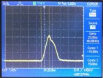
PWMOUT_1_1_040220121641_320x241.jpg

2. Does running the Picaxe in Parallel Task mode affect PWM?
3. If I SUSPEND a task, does the scheduler still spend time on it? (ie will I get a win over a tight, waiting loop in that task, left running)
4. There are restrictions on running PWMOUT *and* SERVO at the same time, but I'm not. Are there any other 'funnies'?

Any thoughts welcome.
Cheers
Matt Lee
 

mleeee

New Member
I've tried PWM and bit banging, and achieve quite reasonable results bit-banging with the unrefined code snippet below
My LED is on Pin B.3.

In practice, making PERIOD 255 produces noticable flicker at 32MHz. (As the cycle frequency is too low.)
255 is the maximum period with Byte-sized variables, remember.
PERIOD=64 gives very good control of brightness levels and very little flicker.
I can see peripheral flicker at PERIOD=128. OK for a static light.

As a fun thought, the FASTER these loops run, the better the DIMMEST light level.
(As the ON time is smallest) I've noticed we can 'see' *tiny* ON times with LEDs.

#Picaxe 14M2
#No_data

symbol Mark=b1
symbol Space=b2
symbol period=b3

Main:
LET DIRSB=%111111 : LET DIRSC=010111
LET period=128
setfreq m32
DO

Fade_up_down:
'Fade B.3 LED up
Mark=0
do while Mark<= period 'Mark gently increases as ...
let Space=period-Mark '... Space decreases
high b.3
pause Mark 'Mark in period
low b.3 'all off for Space time0
pause Space 'Space in period
inc Mark
loop
'Fade B.3 LED down again
let Space=0
do while Space <= period 'Now increase Space
let Mark=period-Space '... as Mark decreases
high b.3
pause Mark
low b.3
pause Space
inc Space
loop
loop

As you'll see, the MARK and SPACE times are INCremented - so changed by only 1. This gives the slowest change in brightness. You could change 'inc mark' to a 'let mark = mark+delta' if you wanted to change brightness more quickly.
(... but look out for mathematical underflow and overflow (which has caught me out). In Picaxe-world, adding 3 to 254 in a byte variable produces the answer 2, which mucks up endstop tests in loops.)

Notice that this code is 'in-line' and will 'lock-out' other code while its running. Parallel tasks solve this, but parallel task code design is far more tricky. If you want to do Pulse-Width Modulation on more than 1 pin using bit-banging - the code needs careful thought and is not simple.

PWMOUT works far better for controlling brightness, and it runs in the background, once set up.

Matt Lee
 
Last edited:

mleeee

New Member
Parallel Tasks demo on 14M2

I have 4 parallel tasks running, in addition to Main:, on my 14M2.
Each PWM pin is having its duty cycle varied by its own task.

Here's some crushed-up code to demonstrate.

I have some LEDs on the 4 PWM pins, C.0, C.2, B.2 and B.4.

#Picaxe 14M2
#No_data​


Main:
LET DIRSB=%111111 : LET DIRSC=010111
'Set up PWM outputs
PWMOUT C.0,255,0 : PWMOUT C.2,255,0 : PWMOUT B.2,255,0 : PWMOUT B.4,255,0
RESUME 1 : RESUME 2 : RESUME 3 : RESUME 4
;Start tasks
DO LOOP ; and twiddle thumbs
end


Start1:
SUSPEND 1​
;Pause the task at switch-on. Will be RESUMED later by Main:
Do
For W1=0 TO 1023 STEP 5
;gradually increase mark proportion of period
PWMDUTY C.0,W1 ;and adjust duty cycle on this channel
NEXT W1
For W1=1023 TO 0 STEP -5 : PWMDUTY C.0,W1 : NEXT : LOOP
; ... and down again, then repeat

Start2:
SUSPEND 2 : Do : For W2=0 TO 1023 STEP 7 : PWMDUTY C.2,W2 : NEXT
For W2=1023 TO 0 STEP -7 : PWMDUTY C.2,W2 : NEXT : LOOP​

Start3:
SUSPEND 3 : Do : For W3=0 TO 1023 STEP 11 : PWMDUTY B.2,W3 : NEXT
For W3=1023 TO 0 STEP -11 : PWMDUTY B.2,W3 : NEXT : LOOP​

Start4:
SUSPEND 4 : Do : For W4=0 TO 1023 STEP 13 : PWMDUTY B.4,W4 : NEXT
For W4=1023 TO 0 STEP -13 : PWMDUTY B.4,W4 : NEXT : LOOP​


This might help Declan's Lighthouse simulation project up at the top of the thread.

Cheers

Matt Lee
 
Last edited:
Top