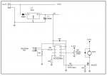
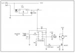
PWM motor speed control.

shamu

Member
Hi all.

I'm having a few problems controling a motor directly from a 08M2.
Ultimately I intend to run the motor through a L293D but I'm trying to get the general jist of how it works first.

My current code looks like this:

#picaxe 08M2
#no_data

pwmout 2,99,400 'pwm acts on pin 2

Main:

pwmduty 2,400

goto main


The 99 & 400 values are what the PWMWIZARD suggests and I think should run the motor at full speed but when I try the program I only get a fraction of max RPM.

With these values should the motor run as though connected directly to + & - volts & can the 08M2 directly supply enough current to run a motor?

Thanks in anticipation
 

Jeremy Harris

Senior Member
The maximum current you can draw from a Picaxe pin is very small, only 25mA maximum, just about enough to light an LED but no more. It won't run a motor directly, in fact you run the risk of damaging the chip if you try it.

You may be able to see the effect of PWM OK to test your code by using an LED and series resistor on the PWM output. The LED brightness will go up and down as the motor speed would.
 

tony_g

Senior Member
+1 as jeremy said dont run the motor directly of the mcu, his led suggestion is better to prolong the life of your chip.if you have some transistors or fets you could have a play with the motor hooked up to those, i have used a modest little motor with a transistor when i was playing around.
 

Bill.b

Senior Member
Hi

This shematic and program may be of some help.
I have used this circuit and program to control from small toy motors and
up to 300watt 12v motors.

The startup routine provide a soft start function.


Code:
'***************************************
'* PICAXE-08M ferris wheel speed CODE  *
'*   Bill.b    21-8-11                 *
'***************************************
symbol counter  = w4
symbol pulsewidth = w1
symbol loopcount = b0
symbol wheelstop = b1

counter = 0
wheelstop = 6  'Number of stops to load wheel


FirstPowerUp: 
gosub startup           'soft start routine

Chopper: 
                                        
	Gosub ReadSpeed  
     	If pulsewidth < 25 then Gosub ZeroSpeed               'Zero out the Speed value if it's already a very low value. 
	Pwmout 2, 100, pulsewidth
	
                           
	Goto Chopper 

ReadSpeed:			'Read pot to set max speed of wheel (set mark/space ratio of PWM)

Readadc10 1, pulsewidth  
                             'Read the Speed value and put it into word varible "W1"
pulsewidth = pulsewidth - 20     'scale the Speed  range 0 - 1023
pulsewidth = pulsewidth * 20/19
If pulsewidth > 1023 then Gosub MaxSpeed    'Hold the value to 1023 if it goes over 1023.  
Return

ZeroSpeed:                                    'Zero out the Speed value to zero.
pulsewidth = 0
Return

MaxSpeed:    
                                'Maximin Speed value to be held at 1023.
pulsewidth = 1023
Return


stopwheel:		'Stop wheel to load. number of stopps determined by Wheelstop variable
			'if controlled slow down required then include gosub slowdown in loop


startup:
	gosub ReadSpeed			'Wheel motor soft start
	pause 20
	for loopcount =95 to pulsewidth step 1
		Pwmout 2,100,loopcount
		pause 100
	next loopcount
	return
MotorSpeed2.jpg

Bill
 

shamu

Member
Thanks for the replies, though I havn't got to the bottom of it yet.
Does anyone know of any PICAXE specific PWM tutorials out there, I havn't ben able to find any.
Thanks.
 

Goeytex

Senior Member
The 99 & 400 values are what the PWMWIZARD suggests and I think should run the motor at full speed but when I try the program I only get a fraction of max RPM
The Picaxe cannot run a motor directly. You need to use a transistor or FET to drive the motor. See the circuit posted above by bill.b

With these values should the motor run as though connected directly to + & - volts & can the 08M2 directly supply enough current to run a motor?
Yes and No

The values chosen indicate 10,000 hz and 100 percent duty and represent 100 percent power. However a Picaxe cannot supply enough current to drive a motor unless the motor operates at 25 ma (not likely) . You may have already damaged your Picaxe by trying to run the motor directly. Let's hope it survived the mistake.

I havn't got to the bottom of it yet.
There is no bottom to get to. You simply need to use an appropriate Transistor or FET to drive the motor as has been explained.

What is the rated voltage of the motor?
What is the current required by the motor at it's rated voltage ?
 

boriz

Senior Member
And what is it's STALL current. (The motor always briefly draws it's stall current at startup)
 

shamu

Member
Hi all.
I'm still banging my head against this PWM thingy!
I have managed to drive a small motor through a BC108 transistor but now need to up the motor voltage to 6V so I can drive a larger motor.
The larger motor draws 3.5Amps when connected directly to the 6V battery.
A couple of problems:
1. When I connect the larger motor the circuit goes completely dead, I suspect due to the voltage drop.
2. The max voltage I can obtain at the motor terminals is 3.5V despite having a 6V battery conected?

This is the code being used, schematic attached.
Thanks in anticipation.


#picaxe 08M2
#no_data

setfreq m8

pwmout 2, 99, 200
symbol motorspeed = w0
symbol potsetting = w1

Main:


readadc c.1, b8 ' Reads pin6 for an analogue value and stores it in variable b1

let potsetting = b8*100
let w2 = potsetting/255

motorspeed = 4 * w2

pwmduty 2,motorspeed

goto main
 

Attachments

Last edited:

hippy

Technical Support
Staff member
I suspect it is mainly a hardware issue and I can't really help with that beyond asking; wouldn't your transistor circuit be better as a low side switch ?
 

Bill.b

Senior Member
with the motor in the emiter side (common emitter) the voltage across the motor will never exceed the picaxe supply - the base emitter volts. i.e 5v - 0.8 = 4.2 volts.

it would be better to place the motor in the collector of the transistor, this would allow the transistor to saturate allowing full 6v supply volts - emitter / collector volt drop, to be applied to the motor.


Bill
 

shamu

Member
hippy, not sure what a 'low side switch' is?
Bill.b, I'll try the motor ont he otherside and see how that goes.
I understand that a FET will work better, can anyone suggest a particular one, I have very limited knowledge of transistors.
Thanks.
 

inglewoodpete

Senior Member
hippy, not sure what a 'low side switch' is?
Bill.b, I'll try the motor ont he otherside and see how that goes.
I understand that a FET will work better, can anyone suggest a particular one, I have very limited knowledge of transistors.
Thanks.
A low-side switch, with the load connected between the collector and the positive rail, needs a current limiting resistor on the base. A BC108 is not big enough for your motor if it can draw 3.5 amps.
 

shamu

Member
Hi all.
I have replaced the BC108 with a FET of type IRF520, and added an LED to show that the PWM is working.
The LED dims & brightens as the pot is turned but the motor runs at a constant speed, the FET appears to do nothing! Some examples I've seen have resistor before the gate, do I need one? What does will it do?
Transistor are the componant I understand the least, almost a complete mystery, any help wouold be greatly appreciated, thanks.
View attachment Motor[4171].pdf
 

Bill.b

Senior Member
This is a circuit i use to control motors from small toy motors up to 300w motors.

MotorSpeed2.jpg

This code is for a ferris wheel, part of a christmas display.
you may need to change section of the code to you requirements.


Code:
'***************************************
'* PICAXE-08M ferris wheel speed CODE  *
'*   Bill.b    21-8-11                 *
'***************************************
symbol counter  = w4
symbol pulsewidth = w1
symbol loopcount = b0
symbol wheelstop = b1

counter = 0
wheelstop = 6  'Number of stops to load wheel


FirstPowerUp: 
gosub startup           'soft start routine

Chopper: 
                                        
	Gosub ReadSpeed  
     	If pulsewidth < 25 then Gosub ZeroSpeed               'Zero out the Speed value if it's already a very low value. 
	Pwmout 2, 100, pulsewidth
	if pin3 = 0 then 			'input from proximity detector. count revs of wheel
		counter = counter + 1

	endif
  	if counter > 15 then  'stop wheel when rotated 15 times
  		counter = 0
  	 	gosub stopwheel   
  	endif
                           
	Goto Chopper 

ReadSpeed:			'Read pot to set max speed of wheel (set mark/space ratio of PWM)

Readadc10 1, pulsewidth  
                             'Read the Speed value and put it into word varible "W1"
pulsewidth = pulsewidth - 20     'scale the Speed  range 0 - 1023
pulsewidth = pulsewidth * 20/19
If pulsewidth > 1023 then Gosub MaxSpeed    'Hold the value to 1023 if it goes over 1023.  
Return

ZeroSpeed:                                    'Zero out the Speed value to zero.
pulsewidth = 0
Return

MaxSpeed:    
                                'Maximin Speed value to be held at 1023.
pulsewidth = 1023
Return


stopwheel:		'Stop wheel to load. number of stopps determined by Wheelstop variable
			'if controlled slow down required then include gosub slowdown in loop
gosub slowdown
	for loopcount = 1 to wheelstop
		Pwmout 2,0,0
		pause 3000
		Pwmout 2,100,pulsewidth
		pause 3000
	next loopcount
	gosub startup
	return

startup:
	gosub ReadSpeed			'Wheel motor soft start
	pause 20
	for loopcount =95 to pulsewidth step 1
		Pwmout 2,100,loopcount
		pause 100
	next loopcount
	return

slowdown:					'wheel motor slow down - for fast slow down change step value or pause

	pause 20
	for loopcount =pulsewidth to 25 step -1
		Pwmout 2,100,loopcount
		pause 100
      next loopcount
 	return
Bill
 

Bill.b

Senior Member
the MOSFET is the IRL520, this is a logic level fet designed for a low gate volts.

Your motor should be in the Source of the MOSFET not the drain.

The drain to gate volts is what switched the fet ON.

Refer to picaxe interfaceing circuit manual page 8

Bill
 

erco

Senior Member
If you can afford to lose ~2 volts overhead, these $4 L298 H-bridge modules work very well, and provide forward, reverse, coast & brake functions for 2 motors using PWM from most any micro, incl Picaxe:
http://www.ebay.com/itm/L298N-DC-Stepper-Motor-Dual-H-Bridge-Drive-Controller-Board-Module-for-Arduino-/380520063503?pt=LH_DefaultDomain_0&hash=item5898c3620f

The two outputs can be paralleled for higher current, per http://www.datasheetcatalog.org/datasheet2/2/052daje928cw7pc0uqs1ipyryppy.pdf

Demo: http://www.youtube.com/watch?v=fL0O0_5ef_k
 

Goeytex

Senior Member
The IRL 520 is the one recomended by techsupplies and is the one used in on the CHI035A
Yes, but as an N-channel MOSFET, the motor belongs in the drain side, not the source side.

Your motor should be in the Source of the MOSFET not the drain.

The drain to gate volts is what switched the fet ON.
You have the drain and source confused. It is the gate to source voltage that turns the FET on. (Vgs)
 
Last edited:
Top