PWM Motor Control, MOSFET getting VERY hot?

vshortt

Senior Member
PWM Motor Control, MOSFET getting VERY hot? - SOLVED!!!

Hi all, it's been a while since I've posted, but I hope someone can shed a little light on my latest project.

This is a simple project using a 20X2's PWM function on C.5 to manage the speed of a fairly high powered blower motor. The motor is rated at 12V 6A max.

The code is very simple. the PWM duty varied by two switches, the period is set at 250 for a PWM cycle of 4Khz, which I thought would be fine.

I have a realable 5v signal at the chip, and have added a large 4700uf Cap to ensure stability.

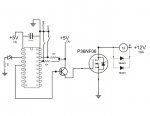
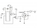
I am using a P36NF06 MOSFET by STmicro as the fan control, switching it with a simple 2N222A npn signal transistor, fired by pin5(pwm) from the 20x2.

When I use the setup to just test (using an LED and resistor as the load) all is well. When I use the motor, the MOSFET seems to be fine at either full power or no power, but the moment that a PWM signal is used to vary the motor speed, the MOSFET gets quite hot - so hot you can't touch it. This MOSFET is rated at 60V, 30A, with a gate threshold of between 2 and 4 volts, so it should be sufficient. Can anyone give me an idea as to what I'm doing wrong or what is missing in the schematic below? (The LED shown just flashes each cycle to let me know the picaxe is running)

Many thanks!

fan control.jpg

Here's the code:

Code:
Symbol Duty = W0
   Duty = 400  ' start with medium duty
   PWMOut C.5, 249, Duty

TOP:
   GoSub Flash  ' flash the LED on Out0
   SerTxD (#Duty, 13, 10) ' used for debugging student programs
   If PinB.0 = 0 and PinB.1 = 0 Then StopPWM ' if both pushbuttons depressed
   If PinB.0 = 0 and PinB.1 = 1 Then Slower ' if one depressed
   If PinB.0 = 1 and PinB.1 = 0 Then Faster ' if other depressed
       ' no change if neither depressed.
   GoTo TOP      ' continually loop

StopPWM:
   PWMOut C.5, 0, Duty    ' zero the period
   GoTo TOP
Slower:
   If Duty < 20 Then Top ' minimum floor
   Duty = Duty - 15  ' decrease duty
   PWMOut C.5, 250, Duty
   Pause 100
   GoTo TOP
Faster:
   If Duty > 984 Then Top
   Duty = Duty + 15  ' increase duty
   PWMOut C.5, 250, Duty
   Pause 100
   GoTo TOP

Flash:    ' flash LED on Out0
   High C.7
   Pause 100
   Low C.7
   Pause 100
   Return
 
Last edited:

Dippy

Moderator
Which 10K res have you changed to 330R?
Not the ones on the switch?
Boriz meant your pullDOWN resistor.

Probably another example of unsuitable driving - this seems very popular on this Forum.
What is the ACTUAL gate voltage you are driving at? I suspect it'll be comfortably below 5V. Difficult to second-guess as you don't specifiy the BJT.
'Scope it. It's the only way to be sure.
I'll say it again; it's not just the frequency but the slew rate. Slow=hot.

If you are one of the anti-driver fraternity, it's best that an NPN drives low and you use a resistor to pull up.
But that is also way inefficient compared to a proper driver or totem-pole / complimentary emitter driver.

Not only do you have to shove charge in and out , but you have to get the Vgs high enough to get it out of the toaster zone.
To design properly you need a 'scope. No two ways.
 
Last edited:

vshortt

Senior Member
Thanks for the correction Dippy, I changed the pullDOWN resistor on the FET to 330R. The BJT is a 2N2222A signal transistor. Even with the Pulldown resistor changed, It's still hot. I have a few drivers on order. Hopefully this will help things. I assumed it was a gate voltage issue but since I don't have access to a scope, it's hard to tell. My first clue was that applying a full five volts to the gate, the MOSFET runs cool and the fan is running full speed. Without 5v applied, the fan is completley off, the MOSFET is cool. The only thing that changes is the PWM. I was actually hoping that there was a way to change the period and adjust the PWM cycle to make this work. However, the rise and fall of the PWM signal would still be the same and wouldn't supply the properly, leaving me with the same problem.

Is this theory correct?
 

boriz

Senior Member
Not a signal transistor. It's a switching transistor with a fairly low gain (not ideal for emitter follower configuration I would think). And the datasheet say up to 2v drop from base to emitter, when saturated! I bet (on a 'scope) your gate voltage looks like a sharks fin leading edge, peaking at little over 3v.
 

John West

Senior Member
You did put the FET on a suitable heatsink, right? But more importantly, a "gate threshold" of between 2 and 4 volts means the gate starts to conduct in that range, not that it is fully on in that range. The device you specified is not designed to conduct substantial current at ~4.3 volts, especially if it is being turned rapidly on and off. It is NOT a logic level drive FET.

It looks to me like that NPN transistor needs to have 12V on its collector, not 5 volts. Then the FET would be turned on fully, instead of acting like a power resistor and dissipating heat all the time. So perhaps the problem is just a typo in the schematic.
 
Last edited:

MPep

Senior Member
In addition to John West's post/reply, I would also recommend adding a PNP to discharge the Gate-channel capacitance as fast as possible. Remove the 10k/330R resistor. Drive the Base with the same signal as the NPN Base one.

Why as fast as possible, I hear you ask?
Well, as long as the FET is in its linear region, neither fully ON or OFF, then power is being dissipated in the form of heat.
 

Jaguarjoe

Senior Member
How does putting 12v on the collector raise the emitter voltage? The emitter will always be 1 Vbe drop lower than the base voltage. Rather than mess with pull ups and pull downs and NPN's and PNP's, just buy $1.00 Microchip gate driver and forget about it.
The 1N400x diode across the MOSFET is not doing anything. It belongs across the motor.
 

Dippy

Moderator
Absolutely, and this is where a little reading-up on transistor theory is required.

With regards to the MOSFET; maybe vshort hasn't typed in the full part no. name? (benefit of the doubt? :) ).
The STP36NF06L is a logic level.

But even so, as mentioned above and by me (and in other places a hundred times), the gate volts level will NOT be high enough to stop it being a heater using your design - even a PNP combo esp from the 12V would be better. Heed what JJ said wrt NPNs.

If you used the transistor as a low-sided switch (and a different bjt would be better) you'd improve things.
But with risk of repeating myself again and again the efficiency of your driver is a combination of voltage , slew rate and current handling.
Get a driver, supply it with 12V, follow any data sheet instructions wrt decoupling and layout and your problems will disappear - job done.
If it's for education and you want to get your teeth into driver theory (good for you) then study totem-pole and complimentary emitter designs.
It's not hard, but you have to understand basics.
 

John West

Senior Member
There appear to be two versions of the FET under discussion. The one specified by vshortt is not the "L" or low voltage version, but the standard version. Therefore it needs a higher gate voltage for full turn-on. The circuit configuration I suggest would use the NPN transistor as a level shifter to drive the FET to its required voltage.

The exact wiring configuration would use the NPN transistor as a pull-down of about a 1K resistor that is tied to the 12 volts rail, meaning the emitter would be tied to ground and the collector would tie to the positive rail through the resistor. The connection point between the NPN collector and the resistor would feed the FET gate. (The 10K pull-down already on the gate would be removed as it would no longer be able to perform its function.)

NOTE: This configuration would leave the fan turned on when the PICAXE circuit is turned off, if 12 volts is still applied to the circuit. It is a "fail-on," not a "fail-off" circuit. This isn't normally good engineering practice, just a possible way of using what you have on hand to get the circuit up and running without overheating.
 

vshortt

Senior Member
Dippy, the full part number is P36NF06. It's not the logic level mosfet (which was an ordering mistake on my part) oh well :)

I think the idea of just ordering a MOSFET controller is the right idea, so thats what I did. We'll see how well it works when they come in today.

Oh, and the 1N4001 diode is just in the wrong spot on the schematic. It's between the two poles of the motor. I believe this is called a flywheel diode or something, right?

please pardon the ignorance, this is my first foray into using mosfets in a circuit that consumes more than an amp or so.
 

vshortt

Senior Member
There appear to be two versions of the FET under discussion. The one specified by vshortt is not the "L" or low voltage version, but the standard version. Therefore it needs a higher gate voltage for full turn-on. The circuit configuration I suggest would use the NPN transistor as a level shifter to drive the FET to its required voltage.

The exact wiring configuration would use the NPN transistor as a pull-down of about a 1K resistor that is tied to the 12 volts rail, meaning the emitter would be tied to ground and the collector would tie to the positive rail through the resistor. The connection point between the NPN collector and the resistor would feed the FET gate. (The 10K pull-down already on the gate would be removed as it would no longer be able to perform its function.)

NOTE: This configuration would leave the fan turned on when the PICAXE circuit is turned off, if 12 volts is still applied to the circuit. It is a "fail-on," not a "fail-off" circuit. This isn't normally good engineering practice, just a possible way of using what you have on hand to get the circuit up and running without overheating.
John, I tried your option and it ran a little cooler, but you're right, it fails (and starts) in an on position and that won't work for this particular project. I sure appreciate all of the tips from everyone! Thank you all!
 

fernando_g

Senior Member
Probably another example of unsuitable driving - this seems very popular on this Forum.
.
Sad, but very true.
Probably a perfect time to make a sticky write-up about this issue.
I volunteer to write it.....Quite busy right now, I hope I have some spare time this coming weekend
 

Dippy

Moderator
I posted a very basic 2-page starter 'guide' a while back just to get people started, but it's apparent that it fell on sandy soil.

The trouble with these things is where to stop. And they tend to disappear.
I tried to keep mine really basic, whereas it was tempting to drivel on for pages at which point people would then start asking me to explain my explanation - thus is becomes self-defeating.

In my little folder I probably have 200 pages of maths, physics and electronicky discussions on MOSFET driving. Lordy, I even do it as a living.
You could discuss the Glenn Miller effect with affects the tuxedo junction.


All I would advise if you want to have a go is keep it simple; do a Novice, Intermediate and Advanced as 3 separate papers. 10 pages would be well OTT for this Forum. I surrender....
 

vshortt

Senior Member
I thought I would go ahead and post the solution to my problem. It all had to do with the flywheel diode across the motor.

Part of the downside of being a simple hobbyist and learning as you go is not fully understanding the function of a part in a circuit. I must admit I have been guilty of putting a part in a circuit without understanding its' function simply because a schematic I was using had it on there. Thats fine until you start making a circuit from scratch. This is where I was bitten.

I did have the diode in place, but it was under-powered and had a faulty connection. The reason I'm posting this is because I wonder how many other amature's out there have been bitten by this when buiding a mosfet circuit. While using a gate trigger IC is a great idea, it wasn't my problem. The picaxe was actually able to pump enough voltage into the MOSFET all by itselft to fully open the gate. (I was able to get a hold of a scope over the weekend to verify that, while the PWM wave wasn't anywhere near perfect, it was sufficient to saturate the gate). So here's what I learned after talking to a professional electronics tech that was kind enough to sit down with me and my little circuit:

He explained the flywheel diode like this:

A motor is essentially a generator when no power is being sent to it to turn it. the "power" side of the PWM signal turns the motor on and it starts to spin. the "rest" side of the PWM signal ther is no power being sent to the motor, but it's still spinning. This spinning action CREATES electricity, even if it's just a small amount. the flywheel diode is there to dissipate that energy. If it's not there, that energy is sent back down the line to the MOSFET. the MOSFET is then forced to dissipate that electrical energy somehow, so it creates heat. To further exascerbate the problem, the MOSFET then has to overcome this energy when it's turned back on to make the motor spin again, driving it even harder. Without a good flywheel diode, the MOSFET gets hot and eventually just burns up. Using a diode that is too small will cause it to get hot meet it's avalanche threshold and pass power back to the mosfet, making it hot too.

So, my solution was to put two N4001 diodes in paralell across the terminals of the motor, effectivley doubling the capacity of the flywheel diode. Voila! no more hot mosfet, no hot diodes and the circuit works a treat even without the MOSFET driver IC!

I just wonder how many other people have been banging their head against the wall because of this little diode issue. Chasing the white rabbit of the PWM signal was a great learning experience, but it wasn't the problem!

Antyway, here's the finished circuit (at least the mosfet part) - I hope someone else can have the light-bulb-over-the-head moment I did thanks to this post. (the pic without the resistor on the PWM to gate trace is correct)

It may not be 100% electronically correct, but it works perfectly!

new-1.JPG
 

Attachments

Dippy

Moderator
Glad you got it working. Motors are fuuny old things; inductors/generators/noise-machines.

I'm still surprised that you're really getting that MOSFET full on with that driver.
I'm just doing an H bridge (work out where your energy goes in that) and my MOSFET gate currents in and out are peaking at 5Amps, whereas your gate 'discharge' route would only allow tiddlyamps.
Did you 'scope the gate voltage?
If you can manage ~200nS transition with that drive then you've invented a new branch of electronics.
;)
Anyway, well done so over-and-out :)
 

vshortt

Senior Member
I'm not sure about the tiddlyamps. I can tell you that the diode is discharging between 1 and 1.4 amps at any given setting. I did scope the PWM from the picaxe and it's nothing spectacular. I can see how using it to drive the MOSFET driver IC would be more efficient. I think what makes it acceptable in my circuit is that I'm using such a large MOSFET, but only running a total of about 4 amps at full power. The MOSFET gate does reach saturation, but not immediatley. the PWM looked like a jagged shark's fin, peaking at 5Volts. a larger capacitor at in the power supply would probably smooth things out a bit. Even though the gate requirements are much higher according to the datasheet, I'm getting what appears to be full saturation in all but the lowest duty cycles (which don't run the motor anyway). Essentially, the PWM cycle is between 50% and 100% in order to get the motor spinning at the required RPM's to move air (it's an impeller style blower motor), so it works for me. I've tested it up to 8 amps with no issues and only mild heating in the MOSFET. Thats 3 times more power that it will ever see. BUT, I wasn't happy with that so I changed my MOSFET at the last moment, opting to go with a FDB8447L N-channel. Of course, this is a logic-level MOSFET so it solved many problems and it isn't shown on the schematic.

But to qualify my previous statement, the circuit DID indeed work to satisfaction with the original MOSFET. the change was less about circutry workings and more about the fact that the new MOSFET was an SMD device. I happen to run across 4 of them in my "junk" drawer. It's capacity is lower (14A advertised) and the logic-level gate probably solved more problems that I realize. I can say that they run cool to the touch, even without a heat sink, so they work well.

I'm confident that I've not invented a new form of electronics!

H-bridges are still the big-harry-monster to me, so I've not dealt with one yet. I understand the theory behind it and will end up making one eventually, but I'm not to the robotic's building stage in my tinkering yet.
 

Goeytex

Senior Member
Good you got a solution.

But your circuit is still inefficient. Invest $1 in a Mosfet Driver and get rid
of that silly transistor. That is just simply a bad way to drive a MOSFET in
a motor control application.... Period.

Did I mention a MOSFET Driver ?
 

vshortt

Senior Member
I guess I just don't see what I would gain with circuit #2 in the pic below, the top circuit is EXACTLY what I'm running right now. If there's a substantial advantage to the bottom circuit, I'm not opposed to using it, I just don't see what I would gain.

I'm open to an education here. I know that the second circuit will provide a cleaner PWM signal, but to what advantage if I'm getting sufficient saturation with the top circuit? will the mosfet last longer with the bottom circuit? This thing is going to be running constantly for up to 4-6 hours in an mobile environment running off of an aircraft's electrical system (not a perminant installtion so no FAA approval or STC required, not critical equipment and it's being driven from a circuit breaker controlled plug.. I'm covered in that aspect - I'm a com'l rated U.S. pilot and have the safety aspect handled.)


So what would I gain, other than a more expensive circuit, with the bottom schematic? I know it's only a $1.31 for the chip and the circuit isn't that much more complex, but I'm making 15 or 20 of these little boards, so if there's a big advantage I'll include the driver IC.

CIRCUITS.jpg
 

Dippy

Moderator
I'm thoroughly confused.

Post 20 : "the top circuit is EXACTLY what I'm running right now..." ("Direct Drive")
is different from
Post 16 : "Antyway, here's the finished circuit (at least the mosfet part)"

Hence my comment about "tiddlyamps" and "I'm still surprised that you're really getting that MOSFET full on with that driver"
In the circuit in Post 16 your charge is via an NPN hence Vg max = 5-Vce = <5V into a non-Logic MOSFET.
And your Gate is discharge is via a 10K resistor Id = (5-Vce) / 10000 = tiddlyamps.
This would mean that the MOSFET is spending a long time as a VCR = hot if the load is significant.

Now you are saying direct from PICaxe into a logic MOSFET.
Is this where your "jagged shark's fin" comes from in Post 18?

I assume you only have a low current motor? (regardless of your quoted PSU spec?)

A shark's fin shape still means a significant amount of time is spent as a resistor.
Also it confirms the PIC's inability to drive the gate hard.(Hardly surprising).
Your circuit is only surviving because of the PIC's output mode current drive limitations.
If it were lower impedance/resistance , but still the same abs current limitation it would pop.

Also, my calcs show that with the FDB8447L at a Vg of 5V and a (for example) slow 2uS transition time that your peak gate current is under 30mA.
You have been saved by luck.

Anyway, if it works then carry on. I'd still use a driver for reliability and longevity.
I've had enough of MOSFET (and IGBT) driving now. I spend most of the day designing this stuff so I need a break.
All the best.:)
 

Goeytex

Senior Member
You gain a lot of advantage using a MOSFET diver. Mostly in efficiency. The motor, MOSFEt and Diodes stay cooler and don't have
to work as hard. Less power is consumed for a given amount of work. Better reliability due to less heat and electrical stresses.


But that MOSFET driver is not really the best choice. If you really want an SMD Driver then consider the
FAN3121TMX instead. You have the CMOS version (CMX)that require an input trigger signal of at least 2/3 Vdd
meaning that if you changed VDD to the Driver to 12V or Upgraded to a better non Logic level FET that requires 10v for
adequate efficient switching, then 5v from the Picaxe would not trigger it. The TMX is TTL and is what you want.

How may I ask did you select your MOSFET and Driver Combination ? You have a 50 amp Logic Level FET, being driven by a 9 amp
Mosfet Driver in circuit that drives a motor that draws no more than 5 amps ? Sometimes over kill is good, sometimes not.

The advantages of MOSFET Drivers have been discussed here so many times I can't count them. And I'ts sometimes amazing at the
resistance that both newbies and those that should know better have to using one in their projects. I suggest you take the time
to read the threads here that discuss MOSFET drivers. Look at the following links and educate yourself on MOSFET basics and how to properly
select them and drive them. Learn the meanings of:

Drains to Source Resistance.
Total Gate Charge
Gate to Source Threshold Voltage
Thermal Resistance
Linear Region

These are the some of the factors to be considered when selecting a MOSFET / Driver Combination.

http://focus.ti.com/lit/ml/slup169/slup169.pdf
http://ww1.microchip.com/downloads/en/AppNotes/00799b.pdf
 
Last edited:

Dippy

Moderator
"Gate to Source Threshold Voltage"
- oh Lordy, this is one thing that I wish so many people would read the Data Sheet about. It is misunderstood so many times.
I'm off... pub open.
 

srnet

Senior Member
This thing is going to be running constantly for up to 4-6 hours in an mobile environment running off of an aircraft's electrical system (not a perminant installtion so no FAA approval or STC required, not critical equipment and it's being driven from a circuit breaker controlled plug.. I'm covered in that aspect - I'm a com'l rated U.S. pilot and have the safety aspect handled.)
Mobile environment from an aircrafts electrical system ?

Strange words, is it to be used in flight ?
 

vshortt

Senior Member
srnet, the strange wording is the reult of me posting from a tablet and not re-checking before I post. Yes, it will be used in flight. I do not wish to debate the positives or negatives of safety/certification/other of where it's being used. If it sets your mind at ease, think of it being used in a car, with a 12v DC system. It won't be used in any of the 24V planes.

Dippy, sorry to wear you out. In my feeble attempt at trying to keep the conversation simple I managed to compeltley muck it up. I apologize.

Goeytex, my selection is merely based on what I have available right now. Are you saying that if I changed vdd to 10V rather that using the 5v shown it would function as advertised? I'm not resistant to using it in the circuit. Again, it has to do with understanding the value. I want to do it right, but more importantly I want to know why it's right. Part of the fun of learning electronics is gaining undertanding.

At this point though, I think I'm ready to stop messing with the whole thing. All I'm doing is upsetting everyone (and driving Dippy to the pub). I'll go read now.
 

Paix

Senior Member
@Vshortt, Not a bit of it. Dippy has this recurring dream where people ask about driving MOSFET devices and he explains at great length, with great regularity. I think that the dream has become a bit of a nightmare, best avoided. And absolutely nothing to do with your upsetting him I'm sure.

It's a little understood area and Dippy has lost faith in most of us ever getting adequately to grips with it before he tears his hair out - on the basis that he has any at the present time of course.

Don't give up.
 

Goeytex

Senior Member
Are you saying that if I changed vdd to 10V rather that using the 5v shown it would function as advertised?
No. I'm saying it would NOT work in your application IF you changed VDD to drive a FET gate at 10 Volts. That is the difference between CMOS logic and TTL logic. It will certainly work advertised by the manufacturer but maybe not as you expected.

You seem like a real smart guy. But you may be out thinking yourself on this a bit. . When experienced folks give you advise on something you have limited knowledge of, it may better to look for reasons to accept the advise instead of looking for reasons not to.

Why is it right? Do you have a couple of years to spare for the study of semiconductor theory and another 10 - 15 more getting getting some practical design experience?
 

vshortt

Senior Member
Okay, I think I can see the advantages of using the driver IC. the added efficiency does make sense. Goeytex, you mention the use of the fan3121TMX, and I see why using the TTL level driver over the CMOS driver would make sense, so lets test my thought here:

I have on hand some fan3122TMX'es - which is the non-inverting version of the 3121. So my thought is this, if I use the non-inverting version, all I would need to do would simply be use the duty settin in reverse to get the same effect, correct? Since it's a PWM signal, it would fire opposite of the inverting output. Is this correct?

One question at a time here. I'm reading and learning as I go so as to waste a little of everyones time as possible.

Please don't mistake my frustration for lack of appreciation for the help. I appreciates everyone's help. Dippy has helped me several times on this board, I continue to appreciate his contributions as well as everyones.
 

Goeytex

Senior Member
I have on hand some fan3122TMX'es - which is the non-inverting version of the 3121. So my thought is this, if I use the non-inverting version, all I would need to do would simply be use the duty settin in reverse to get the same effect, correct? Since it's a PWM signal, it would fire opposite of the inverting output. Is this correct?
I'm not really sure what effect you are referring to, but in a nutshell ....

With the inverting driver, a High signal to the Mosfet driver puts a low signal on the Gate of the
MOSFET turning the motor OFF. Here, a lower duty cycle makes the motor run faster.

With the non-inverting driver, a High to the MOSFET Driver, puts a HIGH on the gate of the MOSFET
turning the motor ON. Here, the higher the duty cycle the faster the motor runs.

Select the one that gets the effect you want. IMO it is easier to manage the non inverting setup.
 

vshortt

Senior Member
Right, we're on the same page. I'm talking about the PWM signal between the driver and the MOSFET.

Okay, second question:

on this driver, if I'm supplying 5v to VDD and leaving the enable pin floating, am I going to get the Vgs up to the requried voltages quickly? (I think the answer is yes, if I'm looking at the datasheet for the MOSFET right. It shows vgs(th) at 3V before drain to source starts really "flowing"

Dippy, if I'm understanding the Gate to Source Threshold properly and am looking at the graphs on the datasheet for this MOSFET correctly, 4v at the Gate should allow full saturation and a complete "short" between the drain and source, allowing maximum power through the MOSFET. is this correect? If so, I deduce that I need to be supplying at leat 4v as quickly as possible. Using the IC driver (With the recommended ceramic Capacitor of 1uF across Vdd and GND) I should be able to do this.

Here's the datasheet:
http://www.fairchildsemi.com/ds/FD/FDB8447L.pdf

Looking at the datasheet for the 3122TMX, the INx Logic Low Threshold is .8 - 1v and the High Threshold is 1.7 to 2.0v, which means that, according to what I saw on the scope over the weekend, the Picaxe will be reaching the minimum threshold to start the propogation process for the driver early in the "shark fin" pwm signal. (Sorry, I don't remember the time scale we used, but it reached .8 almost immediatley.) so this combination should create a fairly square PWM signal to the mosfet as compared to whats coming directly out of the picaxe alone.

I looked at the propogation delays, but since I don't have the timings from the PWM on the Picaxce, I can't calculate how long the mosfet will spend in transition (acting like a resistor), but I'm guessing it will be something close to the average stated on the driver datasheet (td1 + trise = 46ns)

Do I have my theory right?

Here's the driver datasheet
http://www.fairchildsemi.com/ds/FA/FAN3122T.pdf
 

Andrew Cowan

Senior Member
on this driver, if I'm supplying 5v to VDD and leaving the enable pin floating, am I going to get the Vgs up to the requried voltages quickly? (I think the answer is yes, if I'm looking at the datasheet for the MOSFET right. It shows vgs(th) at 3V before drain to source starts really "flowing"

Yes - the threshold (maximum) is 3v - so that is when the current starts to flow.

Dippy, if I'm understanding the Gate to Source Threshold properly and am looking at the graphs on the datasheet for this MOSFET correctly, 4v at the Gate should allow full saturation and a complete "short" between the drain and source, allowing maximum power through the MOSFET. is this correect? If so, I deduce that I need to be supplying at leat 4v as quickly as possible.

Looking at figure 4, On-Resistance vs Gate to Source Voltage: By 4v it's down to 10 milli-ohms - but it carries on decreasing as the gate voltage rises. It will be coolest with Vgs at around 10v.

Here's the datasheet:

I looked at the propogation delays, but since I don't have the timings from the PWM on the Picaxce, I can't calculate how long the mosfet will spend in transition (acting like a resistor), but I'm guessing it will be something close to the average stated on the driver datasheet (td1 + trise = 46ns)

The vast majority of the capacitance you have to deal with is in the MOSFET - the driver should switch pretty quickly. The higher voltage you use on the gate and the slower the PWM signal, the less time the FET will spend in the linear region.

A
 

vshortt

Senior Member
Okay, so my next question is this: how do I supply the driver with more than 5v to trigger the gate with? the IC driver datasheet says that Vdd can be between -0.2v and 18v. so do I connect Vdd to 12v, leave enable pin floating, Connect PWM from piaxe to IN?

I thought this made sense, but I can tell you that the IC driver didn't like being supplied with 12v. (I killed one, have 9 more).
 

Andrew Cowan

Senior Member
I haven't used that driver before, but I would have thought:
- Vdd to 12v
- IN and EN to PICAXE outputs
- GND to ground

I don't know why one of your driver died at 12v - it says it is Ok up to 18v on Vdd...

A
 

Dippy

Moderator
If you look at figure 1 and 2 in the Data Sheet you can calaculate an approx value of DS resistance at Vgs=4V.
It certainly ain't a "short" or full "saturation" , but it will be fine for your little load.
What sort of power loss is there in the MOSFET if the Rds is 0.01 Ohms?
Do the calcs.. does it matter?


If you drive the Gate properly there is no "shark fin".
The "shark fin" is evidence of inadequate drive current.
Which is entriely predictable when using a weedy PIC output drive.

The driver chip will push-pull far 'harder' than a Micro Output driver.
Yes, if applied correctly, you will get a very sharp duty wave going to MOSFET gate.
Your MOSFET has a relatively small total gate charge so rise and fall will be very rapid.

"I looked at the propogation delays, but since I don't have the timings from the PWM on the Picaxce,"
- it's fast, very fast , maybe a handful or two of nanoseconds, and the on-off hystersis is less than a volt so the driver will trigger even faster.
Sweat not :)

For your task a 5V Vdd looks fine.
Try it first before meandering onto higher drive voltages.
Yes, they will be better, but are they needed?
I, too , don't know how you popped your driver at 12V....?
Did a big fat transient come along?
I always zener/TSR protect my designs.
(Confession: I did POP a driver yesterday :mad:)


Now that you have got your teeth into PROPER driving I just want to add that circuit layout will be your next annoyance.
Keep Driver--Gate track as short and fat as possible. Don't have any arty-farty 45degree mitres. Make it straight as possible.
You want to minimise inductance in that track. Keep it away from signal tracks/traces.
If you suffer from painful RFI/EMI then this is usually that your switching is now TOO fast.
Can you believe it? All that effort and now it's too bleedin' fast. :)
Add a 10 to 30 Ohm resistor in the track and this reduces switching speed = reduced harmonics.

I'm afraid MOSFET and IGBT driving is a trade off. Too fast = RFI/EMI, too slow hot = FETs.

One last thing which most people forget about (or don't realise).
If your duty pulse is 100uS long it barely matters a jot whether you switch at 70nS or 100nS.
On the other hand a 100nS transistion time will reduce your RFI/EMI radiated.
So, just have a think. It's not a race to have the fastest , it's a neccessary design compromise.
Even in the electronic power control of electric vehicles ....

One even laster thing; to REALLY nail driving you need a REALLY fast 'scope.
 

John West

Senior Member
Zzzzzzzzzzzzzzzzz.... ;)

Actually, that was an excellent reminder of what to do and what to avoid doing when dealing with power MOSFETs. Each item mentioned is important to doing the job right. Thanks for taking the time to list them.
 

vshortt

Senior Member
Okay, I think I have a better understanding of how a MOSFET works. I appreciate evryones input. Here is the final circuit (complete this time) - take a look. I'd really like to make it as bullet-proof as possible, so what protections should be added?

Dippy I know you said I don't need to run the driver at 12v, but I'm going to go ahead and do it anyway, just in case the load changes on the MOSFET (like larger fan etc..) might as well be safe, right?

new-2.JPG
 

vshortt

Senior Member
Figured out why I popped it at 12v. the last ceramic 1uF cap I had was damaged. Took it out of the equation and it powers up fine. but I have to have one there. They recommend a ceramic cap, but I don't have one. I do have some small electrolytic caps, is there any reason why one of these wouldn't work as long as they're rated for the volages?
 

MartinM57

Moderator
I'd tie the EN inputs of the drivers to Vdd just to make sure that there are no nasties in the circuit that can overcome the 100K internal pullup inside the drivers.
 

Dippy

Moderator
Remember the FAX3121 Data Sheet you linked?
Read bottom of page 14 to top of page 15.
It answers your question perfectly.
You posted it , so I thought I'd better read it.
Maybe you sh ... no I won't say it.
:rolleyes:


This capacitor, other than bypassing/decoupling, acts like a high-speed local power reservoir.
So, when the driver needs some fast oomph it can draw on this local capacitor.
AND it means power transients on power tracks are HUGELY reduced.
The ESr has to be low to allow the oomph, ditto low impedance behaviour with ESL.

X7R and better dielectrics give the best fast response with their low ESR/ESL behaviour.
X7R and above also have superior high-speed characteristics compared to inferior/cheaper dielectrics.
An electrolytic may help a bit but really doesn't cut it. Don't bodge.


And now, my hippy analogy... (ta daaa).
Imagine you needed a super high power flush on your toilet with 6" diameter pipes.
You could plumb it into the mains water and get a reasonable gush but the mains pipe simply couldn't give enough to your 6" to let it really do it's job.
But, just imagine instead, if the mains water was topping up a massive water tank on the roof of your house.
The instantaneous (albeit brief) flush would be huge.
AND there would be less transient load on the mains water system.

Yes, the flushes would be every now-and-then but, as you know, so are gate drive pulses relatively.
 
Top