This technique works very well with almost no noise from the fan and near 0-100% control (or as slow as the fan can turn without stalling).
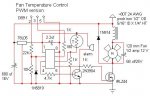
It is an adaptation of a switching power supply. The choke stores energy and releases it to the motor during the off time of the pwm, the 68 uf cap is, for all practical purposes, a short to the 7,000 HZ pwm frequency. (normally the choke would connect to the switching transistor in a typical high side switch - but this works with a N channel mosfet to take advantage of their better specifications - and to replace the already built very slow picaxe fan control that is already cooling my computer (I just have to add the inductor cap and diode to what is already there).
The one K resistor on the gate of the mosfet is just there because the computer cooler once had a darlington transistor and it doesn't detract appreciably from the mosfet switching speed .
The code, as shown, is for a 10K potentiometer that is replacing the thermistor and resistor divider for testing. The actual values for switching points will have to change to work with the thermistor, since a 1K themistor never goes to zero ohms or infinity - and a pot is a lot easier than trying to make a test oven to calibrate it.
The layout is not critical - but that is assuming you know enough to use good practice when laying it out . . . the picaxe should connect to the supply points as shown in the schematic. It doesn't do to have heavy pulsing currents flow through axe on the same wires as are carrying the fan motor current.
The inductor is "unknown" value - I had a number of already wound small toroids I was using for another experiment, and put several of them in this circuit. One millihenry is probably in the ball park.
The code is written to turn on the fan (ultimately at 70F) and ramp the speed up proportional to temperature (maxing out at around 88F). There's a line or two to turn off the fan entirely when the temperature is low enough that the power supply can can cool the case - there's a little hysteresis written in to turn the fan back on at a higher point than it turns off at to prevent it from pulsing on and off. There is a "goose" (short blast of voltage to get the blades turning from a dead stop and inherent friction). An audible alarm buzzer tells me the thermistor is open or shorted or if the temperature is approaching melt down. The former failure mode also puts the fan "on" with full DC power (no pwm).
Debug, while useful for calibration and such, will interfere with operation while information is being transferred to and from the axe.
My fan is a 12 V, large (120 mm) type that draws about 1/2 amp at 12 volts
While it makes no noise to speak of - there is a slight singing that occurs before the blades come up to speed from a dead stop or when it is held stalled. It is only noticeable because the fan is 12" from my ears on the breadboard and won't be noticeable inside the computer case.
My computer (tower case) has one of its side panels cut out and replaced with a 14" square furnace filter to keep cat hair at bay - otherwise the fan would suck crud into the every orifice in the case - like CDR and floppy doors.
Code:
'    Adaptation of switching power supply to low side pwm fan control
' this works very well with brushless fans with the addition of
' an inductor in the +12 V to + fan connection, 68uf across fan connections
' with a logic level mosfet switching pwm to ground. (!)
' almost no noise except at the slow speed startup

symbol analogcontrol = 1
symbol analogvalue = w0
symbol pwmport = 2
symbol buzzer = 4
goto runn

runn:

    readadc10 analogcontrol ,analogvalue      'read an analog value into W0 from thermistor on pin 6
    'debug analogvalue

    if analogvalue <= 20 then alarm2    'sensor failure alarm (open)
    if analogvalue >= 1000 then alarm2    'sensor failure alarm (shorted)
    if analogvalue <= 120 then stop1    'fan set to off if temp too low
    pwmout pwmport, 255, analogvalue    'on/off pwm ratio based on temperature
    if analogvalue >= 900 then alarm3    'temperature approaching meltdown
    goto runn

stop1:
    pwmout pwmport, 0, 0            'stops fan entirely when temperature is low
    if analogvalue >= 121 then stop2    'gooses fan into overcoming friction
                            'these lines provide hysterisis on restarting -
    if analogvalue >= 120 then runn    'temperature must be higher than where it cuts 'off
                            'prevents multiple goosing when its on the cusp of
                            'turning on
    goto runn

stop2:
    high pwmport
    pause 50                    'goose
    goto runn


alarm3:
    high buzzer         'turn on buzzer for 1/3 second
    pause 300
    low buzzer            'slow buzzer hi temp alarm
    pause 2000
    goto runn


alarm2:
    pwmout pwmport, 0, 0    'fast buzzer sensor failure alarm
    high pwmport
    high buzzer
    pause 300
    low buzzer
    pause 400
    low pwmport
    goto runn
Attachments
-
 30.5 KB Views: 386
Last edited: