PWM control of brushless fan revisted

gengis

New Member
I've been toying with ideas since Mad Professor brought it up last February. I have a technique that works like a champ. The idea started as a "choke input filter." These were the only way to get filtered DC years ago - there were no electrolytic caps or they were large and dangerous, so you used paper/foil caps in mineral oil and large inductors to filter DC through multistage pi networks.

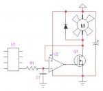
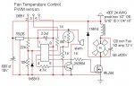
Works like a champ for taking the PWM from an axe - to a mosfet to control brushless fans without all the chirping and odd impeller behavior. Only anomaly was a hell of a voltage spike across the source drain junction of the mosfet - no problemo a diode around the inductors (fan and choke) returns the spike to the power supply and improves efficiency. Voila! the same circuit as you see in "buck type switching converters" just minus the feedback loop.

I'll put a write up of the thing in the finished designs section when I get around to it. The pwm is running along at 7,000 HZ. Using a 1N914 is perfectly acceptable since the flyback pulse contains very little energy. My fan is a one half amp, twelve volt, 120 mm size case fan. No parts get warm while in operation and a heatsink isn't necessary. Only two caveats "debug" may interfere with operation so only use it to see what's happening, but don't expect it to work if you leave it in the code - AND the power supply must connect to the fan/inductor and mosfet source - the rest of the circuit should be laid out as the schematic suggests - letting the power pulses travel down the same wires/traces that feed the axe is asking for problems - especially on one of the solderless breadboards. Bypass the axe as shown.

The inductor specs? I had a number of ferrite and powdered iron cores laying around and just stuffed one with as much wire as it would hold and still look "right." Any kind of high permeability core or "hash" filter choke should work. 7,000 HZ is low frequency - out of the range of laminations but well within the range of powdered iron. I tried several I had laying around and they all worked. I'd guess there's 1,000 mhy inductance in the one I'm using.

68 uf across the fan is not critical at all, 50 -1000 worked fine.

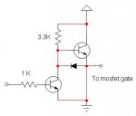
The 1K to the gate of the mosfet is superfluous - I had a darlington in there at one time and that was just a limiting resistor for the base drive. Darlington will work fine, but the efficiency is higher with a mosfet.
 

Attachments

BeanieBots

Moderator
As you say, it's essentially a buck converter.
However, your IN914 is in danger. (Imax ~300mA)
It's current rating needs to be higher than the current drawn by the fan during startup (including the charging of the cap, limited only by the inductor). This is because the current that gets 'thrown back' by the inductor during the off phase will equal the current passed through it during the on phase. The highest value will be for the very first on pulse when the circuit is first powered up.

A fast schottky diode would be a better choice.

EDIT:
I doubt your inductor is "1,000mhy".
Just 80 turns on even a very high permiability core is unlikely to give more than a few 100's of uH.
 
Last edited:

gengis

New Member
You're right about the inductor, I meant to put 1,000 uhy.

I doubt the diode would ever fail . . . the pulse is high voltage without the diode, but very short duration. Lots shorter than the 1 microsecond / one amp surge current the 914 will handle.

A schottky would be the "appropriate" device. But I trust this to last the way it is.

I ran it for hours with no diode, long before I thought to put the scope on it and look for transients. The flyback pulse was >30 volts but so narrow my 30 mhz scope couldn't show the true waveform.
 

manuka

Senior Member
Flooby:"Ouch" on those abreviations. Symbols honouring these early electrical scientists use a capital! Thus the Henry is always shown capital H, Hertz as Hz, and Farad F . Micro µ can even be arranged with ALT +0181 (numeric keypad).

It may seem tedious, but ones technical credibility is often at stake with unit misuse, especially given that lightning fast circuit activity takes few prisoners -overloads can even be lethal if innocently organised. I can get mega spooked out by electrical unit misuse! You may think it trivial, but consider the difference between metric multipliers "m" (milli) & "M" (Mega). Would you prefer a m$ or M$ ?! Such measurement unit blunders have cost "whoopsies" in the style of NASA's $$$$$$$$ 1999 Mars orbiter loss.

Electrical units were late on the arena (mid 1800s) & are hence thankfully internationally standardised. Consequently considerable care should be taken,as metric/imperial cultural excuses that may be tolerated with weights & lengths just can't be offered in electrical fields. You HAVE to be CORRECT... Nifty DIY work otherwise! Stan
 
Last edited:

gengis

New Member
Is it castigate flooby day?

The microhenry was a slip . . .

I still find myself calling them kilo/mega cycles per second, or the old Able Baker Charlie Dog Easy Fox George - phonetic alphabet . . .
 

BeanieBots

Moderator
Is it castigate flooby day?
Looks like it!
Sorry if I sounded like I was slating your circuit. You've done a good job, I'm just worried about that poor old 1N914. It may well survive but it won't be having a happy life. As for Stan's comments. I have to agree. I genuinely thought you meant mH and therefore questioned any other numbers that might have been involved.

EDIT:
Those aren't the standard phonetics either!
 

manuka

Senior Member
Come on guys,this is 2010! The standard NATO phonetic alphabet was adopted in 1965- some 45 years ago. I did all my initial electronic training with kc/s & Mc/s,but Hertz replaced these by the late 1960s. Unless you're now almost ~70 yo. (anyone?), such yesteryear terms should be now as quaint as pounds, shillings and pence...
 

Attachments

Last edited:

gengis

New Member
Built my first crystal set in '52. All the "new" terms didn't catch on right away - it takes time before new revisions of textbooks etc. and then it enters the lexicon. for the rest - I must have been having a "senior moment."
 

papaof2

Senior Member
Come on guys,this is 2010! The standard NATO phonetic alphabet was adopted in 1965- some 45 years ago. I did all my initial electronic training with kc/s & Mc/s,but Hertz replaced these by the late 1960s. Unless you're now almost ~70 yo. (anyone?), such yesteryear terms should be now as quaint as pounds, shillings and pence...
I was but a child when I learned the (then standard) terms (i.e., kilocycles) and phonetics - my friends were reading car magazines, I was reading electronics and science magazines ;-) I learned the NATO phonetics some years later.

And 70 doesn't seem that old when you're only 4 years away.

Time to get back in the attic and remove the rest of the flooring (1/2" plywood sheeting) to finish properly insulating this old house....

John
 

fernando_g

Senior Member
Flooby;
Powdered Iron cores are color coded according to the material type (and thus its permeability). For instance, yellow/white is a #26 material, and a black/black is a #45 material.

If you can tell me what color it is, I can calculate for you the inductance value (just to satisfy your curiosity).
 

gengis

New Member
Flooby;
Powdered Iron cores are color coded according to the material type (and thus its permeability). For instance, yellow/white is a #26 material, and a black/black is a #45 material.

If you can tell me what color it is, I can calculate for you the inductance value (just to satisfy your curiosity).
I buy surplus electronics components to tinker with - This particular core has no color markings on it so the base color is gray or dark gray. Most of the surplus stuff is low frequency & high permeability.
 

LizzieB

Senior Member
Going back to the original topic for a second I also tried PWM'ing a 120mm fan recently, it was a complete waste of time. First I discovered the fan I was using made an excellent loudspeaker, or I guess siren would be more correct, so then I converted to a buck convertor (using a real diode) and discovered that this fan had almost no useable voltage control range. YMMV as they say.
 

boriz

Senior Member
I’m working on a scratch built cooling system for the two dual processors in my PC. As well as displaying the temperature, measured using LM335, it will switch fan power between two states, full and half. Half is achieved using a simple low side series resistor and full by bypassing the resistor with a MOSFET. The threshold will be set in the Picaxe software. KISS!
 

gengis

New Member
Going back to the original topic for a second I also tried PWM'ing a 120mm fan recently, it was a complete waste of time. First I discovered the fan I was using made an excellent loudspeaker, or I guess siren would be more correct, so then I converted to a buck convertor (using a real diode) and discovered that this fan had almost no useable voltage control range. YMMV as they say.
Sorry to hear it. I expected more of a challenge (having given up with pwm last year). I was prepared for a long uphill battle and disappointment at the end of it, so I'm pretty stoked that this is working so well (for me).

I started the project with an intent and strong bias to making it a linear fan control. And just using the axe to set speed via pwm. The conventional wisdom and my own feeling is that bare pwm and brushless fans don't mix.

Linear makes perfect sense in this application. The computer can easily supply the power. My fan is large by case fan standards, and uses a lot of power - but that is a mere 6 watts. If the fan is getting 6 volts instead of 12 the power dissipated in the pass transistor is only on the order of 1-1/2 or 2 watts max - worst case is probably closer to 1/3 power, but still not a great deal. Then at maximum speed and cooling the power in the pass element is virtually nil, so it won't be adding to the overall heat load. mount a TO220 on the fan itself or a small heatsink by the (exhaust) fan and there's no loss to the system cooling.

Just an RC network to integrate the pulses and an opamp voltage follower with its feedback closed around the pass element. Or power op amp voltage follower.

Back to pwm - From what you say, I'd suspect too low an inductance and/or board layout (using my design).

Switching supplies in general are (usually) something of an art to get right. Higher (100 KHZ+) frequency supplies are more touchy about layout, inductor quality, ESR and internal inductance of the filter cap etc..

The IC manufacturer will usually provide a parts list with where all the parts came from as well as an example of a "reference design," showing how it should be done.

I did have a problem with narrow control range - but that turned out to be my test power supply drooping under the load - a "come along" supply fixed that (big transformer cap and diodes with a variac setting voltage - and honest to goodness mechanical magnetic circuit breakers on primary and secondary power).

The singing (7 KHZ) audible in the fan at zero and starting speeds could even be eliminated with a different inductor. One that was physically too large to consider using.

Attached is what was to be the basis for "Plan B" Linear variable speed.
 

Attachments

LizzieB

Senior Member
Flooby, thanks for your comments. Just to clarify, the "singing" was only an issue feeding raw PWM direct to the fan. My junkbox parts PWM to DC conversion worked very well (somewhat to my surprise), the output was very clean, and after some playing about with the L and adding a driver transistor to kick the FET on quickly it was quite efficient. I think the problem comes down to that particular fan having being very well optimized for its design voltage.
 

gengis

New Member
My junkbox parts PWM to DC conversion worked very well (somewhat to my surprise), the output was very clean, and after some playing about with the L and adding a driver transistor to kick the FET on quickly it was quite efficient.
I know; the conditioning ("it can't be done," the way you want to do it) hence: "somewhat to my surprise." Thomas Edison commented a time or two on that idea.

Sorry, I didn't understand, from your post, that you already had a workable solution. Please post it (?).

This (attached) is a mosfet driver or totem pole output that may come in handy. It's "claim to fame" is that one transistor can't turn on until the other turns off - so while it will still switch the mosfet gate (quickly, with no ands, ifs, or buts) it can't cause problems with both transistors being on at the same time (super current spikes on the PS lines) - like an NE555 totem pole.

If you already knew, please forgive me. One of the misconceptions of age - you think you automatically know more than the other guy - a lot like 8-18 year old's in that respect.
 

Attachments

Jaguarjoe

Senior Member
Just an RC network to integrate the pulses and an opamp voltage follower with its feedback closed around the pass element.

Attached is what was to be the basis for "Plan B" Linear variable speed.

I think the inverting and non-inverting inputs to the op-amp are reversed.
 

gengis

New Member
I think the inverting and non-inverting inputs to the op-amp are reversed.
They are indeed and (this time) it is no accident. If the op amp were the only part of the voltage follower, the output would return to the inverting input, but this includes the transistor in the feedback loop, and the transistor inverts the signal.

Using an opamp eliminates the need for the axe to monitor the voltage to the fan. Just connecting the transistor to the integrator with no feedback loop won't work since transistor gain varies from one to another part, and gain varies with both temperature and loading. Using another analog input on the axe could provide feedback and adjust the voltage on the fly - but the code gets more complicated and the response time suffers.
 

nick12ab

Senior Member
I'm working on my own PICAXE-based fan controller but it needs to use the tachometer signal to determine the fan speed like a motherboard does AND apply PWM fan control. I'm just using simple PWM, a logic level MOSFET and a smoothing electrolytic capacitor. The issue I'm having is that when using PWM, the speed reading gets inflated massively, I'm assuming this is because of the PWM noise.

Have you tried to use the tach signal on a fan controlled with your filter - if you succeeded then I may have to get some inductors and use your circuit (I'll be controlling two fans in the final circuit).

The test code I used:
Code:
#no_table
#no_end
#picaxe 28x2
#terminal 19200
symbol sense1 = C.5
symbol sense2 = C.4
symbol fan1 = C.1
symbol fan2 = C.2
symbol count1 = w2
symbol count2 = w3
symbol counter = w4
    setfreq m16
    settimer t1s_16
    high fan1
main:
    count sense1,1000,count1
    count1 = count1 * 120
    sertxd (#counter," - ",#count1,cr,lf)
    inc counter
    if timer = 15 then
        pwmout PWMDIV16, fan1,63,4
    end if
    goto main
The relevant results in the terminal:
Code:
54 - 1320
55 - 1320
56 - 1320
57 - 1320
58 - 45960        'Point where PWM is used
59 - 47640
60 - 47520
61 - 45960
62 - 46440
I have tried different PWM speeds with equally poor results. Of course, in real life the fan does not spin at 45000RPM! It does spin slower than the non-PWM speed as expected. When using a capacitor between the input pin and ground, it either has no effect or completely obliterates the signal depending on value.

The MOSFET used is STP36NF06 ad is being used as a lo side switch. The smoothing capacitor is wired across the fan power connections - I have tried values up to 470µF without success. If you need a circuit diagram, I can do one tomorrow.

If the PWM works in the end, I'll move on to implementing a moving average or something to make the reading more precise.

Added detail: Fan in use is Arctic Colling F12, circuit is on breadboard, fan and PICAXE are both powered by separate switching regulators assembled on stripboard with smoothing capacitors fitted, a decoupling capacitor is fitted to the PICAXE, download cable is AXE026 connected to a real serial port.
 

nick12ab

Senior Member
I've changed the circuit so that now a PNP transistor (TIP32C) is used as a high side switch and it is controlled with a BC238 NPN transistor which pulls down the base with a 330R resistor - a 1k resistor limits the speed of the fan. The issue now is that the PNP transistor gets hot. I'll find a resistor that's a compromise between the two later and report back.


I doubled the period of the count command for greater precision in the test andf changed the formula for calculating RPM to count1 * 60. The results with the high side switch are decent.
Code:
0 - 180
1 - 600         'Powered up
2 - 780
3 - 960
4 - 1080
5 - 1140
6 - 1140
7 - 1200
8 - 1200
9 - 1200
10 - 1200
11 - 1200
12 - 1140
13 - 1140
14 - 1140
15 - 1140
16 - 1140
17 - 1140
18 - 1140
19 - 1140
20 - 1200
21 - 1200
22 - 1200
23 - 1200
24 - 1140
25 - 1140
26 - 1140
27 - 1200
28 - 1200
29 - 1200      'PWM activated, 25% duty cycle
30 - 1080
31 - 900
32 - 840
33 - 780
34 - 780
35 - 600
36 - 600
37 - 600
38 - 480
39 - 540
40 - 480
41 - 480
42 - 480
43 - 480
44 - 420
45 - 600
46 - 420
47 - 480
48 - 540
49 - 420
50 - 540
51 - 480
52 - 480
53 - 3120      'Power supply turned off
54 - 0
The lack of high frequency noise is probably because the tach signal from the fan is open collector so switching the high side doesn't affect the transistor inside the fan.
 

nick12ab

Senior Member
More progress:

Bad - Low duty cycles still create a massive speed reading
Code:
0 - 240
1 - 600
2 - 840
3 - 1020
4 - 1140
5 - 1200
6 - 1200
7 - 1260
8 - 1200
9 - 1200
10 - 1200
11 - 1200
12 - 1260
13 - 1260
14 - 1260
15 - 1260
16 - 1260
17 - 1260
18 - 1260
19 - 1260
20 - 1140
21 - 900
22 - 720
23 - 660
24 - 540
25 - 480
26 - 480
27 - 420
28 - 540
29 - 960
30 - 720
31 - 1620
32 - 1500
33 - 1500
34 - 1380
35 - 1680
36 - 2460
37 - 3660
38 - 7020
39 - 6780
40 - 8160
Using higher frequency PWM (by using lower period in command and by using 16MHz external crystal) helps the situation a bit but doesn't solve it completely.

Using a period of 31 and a duty value of 5 does not cause the problem to happen (5 is the minimum that doesn't cause the problem) and the fan is almost silent (not fitted in the case) but slowing the fan physically by hand will cause the problem to occur so the minimum I can actually use will have to be 6 or 7 to tolerate for the fan dying slowly as fans do.[HR][/HR]Whilst I'm posting, does anyone know whether motherboard irda headers use exactly the same signals as a normal serial port or not? I'll test it myself so don't anyone bother going to the effort of testing it yourself - if anyone definately knows, just post!
 

nick12ab

Senior Member
Whilst I'm posting, does anyone know whether motherboard irda headers use exactly the same signals as a normal serial port or not? I'll test it myself so don't anyone bother going to the effort of testing it yourself - if anyone definately knows, just post!
No, it did not work. The loop-through test worked but the PICAXE could not be programmed and data sent through the IrDA port could not be received with the serial port. A shame as it would have opened up a path to PICAXE project(s) integrated into the PC without using the normal serial port if it had worked.
 

inglewoodpete

Senior Member
PWM-ing a brushless fan is fairly simple - I used a 2N7000 and a 14M a few years ago. You may have to swap fans around until you get one that performs well. I was lucky and got a good one (60mm) first time.

For the tacho, I think this problem was addressed previously. From memory, a spot of white-out ("Tippex"/"Liquid Paper") on the hub, near the base of one of the blades, was used with an LED and phototransistor. Use PulsIn to read the period and then derive the speed from that.
 

nick12ab

Senior Member
Regarding the IrDA, I think that it may be inverted compared to normal serial so I'll try programming a PICAXE through an inverter or an A****** with no inverter later.

PWM-ing a brushless fan is fairly simple - I used a 2N7000 and a 14M a few years ago. You may have to swap fans around until you get one that performs well. I was lucky and got a good one (60mm) first time.
The fan itself performs well with PWM, it's just the tacho that doesn't work well at low speeds only. The tacho signal produces two pulses per revolution and is open drain so using a high side switch is better than a low side switch. I'm assembling my circuit on stripboard which could eliminate the problem if the noise is caused by the circuit being built on breadboard.

Your idea of using Tippex on the fan is unlikely to work as every accessable part of the fan that rotates is white.
 

nick12ab

Senior Member
Some update

I'll be starting a thread in the Finished Projects area at some point in the near future for my speed controller. This is the current state - simply measures the speed without any averaging and makes the fans go slow or fast depending on the position of the toggle switch.
Code:
#no_table
#no_end
#picaxe 28x2
#terminal off
#com 1
symbol rs = A.4
symbol enable = C.0
symbol sense1 = C.5
symbol sense2 = C.4
symbol fan1 = C.1
symbol fan2 = C.2
symbol therm1 = C.6
symbol therm2 = C.3
symbol switchdown = pinA.0
symbol switchup = pinA.1
symbol switchaction = pinA.2
symbol switchtoggle = pinA.3
symbol count1 = w2
symbol count2 = w3
symbol counter = w4
symbol lcddata = pinsb
symbol loopcounter = b10
symbol readvar = b11
symbol bta1 = b12
symbol bta2 = b13
symbol bta3 = b14
symbol bta4 = b15
symbol bta5 = b16
    setfreq em64
    settimer t1s_16
    pwmout fan1,31,127
    pwmout fan2,31,127
    dirsB = 255
    low rs
    output enable
    lcddata = %00000110 : pulsout enable,100
    lcddata = %00001100 : pulsout enable,100
    lcddata = %00111011 : pulsout enable,100
    lcddata = %00000001 : pulsout enable,100
    pause 500
    low rs
    lcddata = 128 : pulsout enable,1
    high rs
    for loopcounter = 0 to 15
        lookup loopcounter,("16 CHARS LINE 1 "),readvar
        lcddata = readvar
        pulsout enable,1
    next loopcounter
    low rs
    lcddata = 192: pulsout enable,1
    high rs
    for loopcounter = 0 to 15
        lookup loopcounter,("16 CHARS LINE 2 "),readvar
        lcddata = readvar
        pulsout enable,1
    next loopcounter
    pause 8000
    low rs
    lcddata = 128 : pulsout enable,1
    high rs
    for loopcounter = 0 to 15
        lookup loopcounter,($C7,"NB  XXXX A  YY",$B2),readvar
        lcddata = readvar
        pulsout enable,1
    next loopcounter
    low rs
    lcddata = 192: pulsout enable,1
    high rs
    for loopcounter = 0 to 15
        lookup loopcounter,(" SYS XXXX A  YY",$B2),readvar
        lcddata = readvar
        pulsout enable,1
    next loopcounter
main:
    count sense1,32000,count1
    count1 = count1 * 15
    low rs
    lcddata = 133 : pulsout enable,1
    high rs
    bintoascii count1,bta1,bta2,bta3,bta4,bta5
    lcddata = bta2 : pulsout enable,1
    lcddata = bta3 : pulsout enable,1
    lcddata = bta4 : pulsout enable,1
    lcddata = bta5 : pulsout enable,1
    count sense2,32000,count2
    count2 = count2 * 15
    low rs
    lcddata = 197 : pulsout enable,1
    high rs
    bintoascii count2,bta1,bta2,bta3,bta4,bta5
    lcddata = bta2 : pulsout enable,1
    lcddata = bta3 : pulsout enable,1
    lcddata = bta4 : pulsout enable,1
    lcddata = bta5 : pulsout enable,1
    if timer >= 4 then
        pwmduty fan1,3
        pwmduty fan2,3
    end if
    if switchtoggle = 1 then
        timer = 0
    end if
    if timer < 4 then
        pwmduty fan1,127
        pwmduty fan2,127
    end if
    goto main
 

Attachments

Top