pulsin then servo
- Thread starter alband
- Start date
That's interesting. My keyboard appears to be on 27Mhz - I couldn't type at first and could hear some noise from my servo. I'd left it on and if I move the keyboard close, the servo moves, hu.
Anyway, I downloaded three programs and have installed one. There doesn't seem much need to install al three yet unless 2 don't work.
I've currently got "Soundcard Oscilloscope" running but can get it to pick up anything.
I've got an old 3.5mm headphone jack plugged into the microphone-in and the negative is connected to the Rx gear's negative and the left channel is connected to the servo pulse line (with a servo connected).
Have I connected to the wrong port?
Is this not my soundcard port?
Found this on their internet page:
The pulse will be way to high wont it. Would it damage the Rx gear to put a POT in it?The signals for the oscilloscope can be internal to the computer (MP3 player, function generator etc.) or from external sources (line-in, microphone). For external sources care has to be taken, not to exceed the voltage range of the inputs. The range is usually only ±0.7V !! If higher voltage need to be analyzed, a voltage divider has to be used. Additional protection diodes are recommended in order to avoid any damage to the sound card and to the computer.
I've sorted the line-in problem, it was just system setting, but I still need to sort that logic level.
74HCxx?
Edit: I've seen the internal circuits of the Rx, its from the analogue age. Tonnes of components, one chip which only has a few pins used. Some may call it beautiful, some may call it a mess.
74HCxx?
Edit: I've seen the internal circuits of the Rx, its from the analogue age. Tonnes of components, one chip which only has a few pins used. Some may call it beautiful, some may call it a mess.
Last edited:
Right, got the oscilloscope working. I just put a POT across the negative and signal of the servo and wound it up until it worked. I'm working on getting a good image. Like I said, My keyboard is on the same frequency as the Rx so whenever I press Prt Scrn it ruins the trace.
All very run though.
All very run though.
Sussed it.
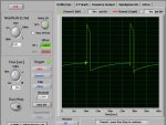
Here is the Rx trace at centred position.
I've noticed that the time base isn't 20ms but about 18 or 19.
This signal however does work on the rate gyro (HH gyro should arrive on Monday - shipped today).
Am working on the PICAXE trace.
Here is the Rx trace at centred position.
I've noticed that the time base isn't 20ms but about 18 or 19.
This signal however does work on the rate gyro (HH gyro should arrive on Monday - shipped today).
Am working on the PICAXE trace.
Attachments
-
 132.8 KB Views: 11
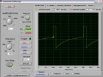
... And here is the PICAXE.
The logic level is higher although this isn't through a 330R resistor (it is coming through the POT though at the same setting). Also the timebase is exactly 20ms (good job PICAXe, good job).
The logic level is higher although this isn't through a 330R resistor (it is coming through the POT though at the same setting). Also the timebase is exactly 20ms (good job PICAXe, good job
).Attachments
-
 133.2 KB Views: 12
The servo was centred but the PICAXE was running this code (no buttons pressed).
So the servo should have been on 150 (centre). I did try changing the value of the PICAXE when I had the gyro connected and it made no difference.
Code:
		servo 2,150
		let b0 = 150
main:		let b1 = b0
		if pin4 = 1 then up
		if pin1 = 1 then down
Cont:		if b0 > 190 then
		let b0 = 190
		endif
		if b0 < 125 then
		let b0 = 125
		endif
		if b0 = b1 then main
		servopos 2,b0
		goto main

up:		if pin4 = 1 then up
		let b0 = b0 + 1
		goto Cont

down:		if pin1 = 1 then down
		let b0 = b0 - 1
goto ContBeanieBots
Moderator
Both of those traces look as if they are AC coupled.
There should be absolutely no vertical movement on the horizontal lines. This is probably a result of using a sound card (AC coupled??) as apposed to a 'proper' 'scope.
Unfortunatley, as the point of the excersise is to determine the difference between the Rx signal and the PICAXE signal, these traces do not help a great deal. Especially as my personal belief is that the problem still relates to level rather than timing.
The PICAXE signal works with a servo but not a gyro.
That proves it's not a timing issue.
If it's not level, then what else could it be?
Last edited:
I too am convinced it's a logic level problem. If you look at the traces the PICAXE high's are a lot higher than the Rx's. Would this be a problem though if the gyro and PICAXE are driven off the same power supply?
Let's think for a minute. We should be able to work out the logic level the qyro needs (as a fraction of VDD) and work out the logic level the PICAXE is giving.
The R'x is being powered of 4 AAA's that are reading a total of 5.82V.
Judging by the traces, the Rx's logic high is, well, I don't know. I think that oscilloscope shows it but I don't understand the units. It's giving me a Vp-p of 1.7ish and a Veff of 400ish. Unfortunately, I have no idea what Vp-p or Veff are.
The PICAXE is running of 5V from a 7805. It's logic high is, well, I also don't know that. It's giving me a Vp-p of 1.8ish and a Veff of 370ish.
On thing that also may be worth mentioning is that they are both running through a POT. The pot is between the signal and GND with the output feeding the audio jack.
BeanieBots
Moderator
That makes it even more confusing if the PICAXE levels are HIGHER
As your 'scope has no established ground reference, I can only guess that the gyro is not seeing a voltage LOW enough to be seen as low.
Have a go using a cap between PICAXE output and gyro input.
Needs to be non polar and as big as possible. 220nF should be OK but bigger if you have one.
As your 'scope has no established ground reference, I can only guess that the gyro is not seeing a voltage LOW enough to be seen as low.
Have a go using a cap between PICAXE output and gyro input.
Needs to be non polar and as big as possible. 220nF should be OK but bigger if you have one.
Still no joy.
I tried a few very old caps. One marked as brown black yellow black red brown. (brown could just be the colour of the capacitor). One large disc ceramic marked as 221J. And one massive cap marked as 104J100V (about the size and shape of a small humbug).
Do you know what those units are. If so, we could work out what logic high and low the gyro needs.
The logic low not being low enough would make sense though. If you compare the traces, the PICAXE's low is higher that 0 for about half the low period whereas the Rx's low is always less than 0.
BeanieBots
Moderator
Everything you ever wanted to know about caps. (inc how to read values)
http://my.execpc.com/~endlr/
For example "104" is read same way as resistors but in pF.
"10" is the 'value' & "4" is the multiplier.
Hence, 104 = 100000pF = 100nF = 0.1uF
As with resistors, you eventually get to the point where you simply "read" them just like reading a word in text.
"If you compare the traces, the PICAXE's low is higher that 0 for about half the low period whereas the Rx's low is always less than 0. "
Only those traces are not REAL. That curve is a result of the AC coupling and does NOT reflect the true DC level. The TRUE servo output from a PICAXE is absolutley flat. However, when loaded with something like a TTL input (maybe like your gyro input) the base level might not be zero. Without a proper DC coupled 'scope, we can only GUESS.
Your test with the largest cap (100nF) might not have used a large enough cap. I've found 220nF (224) to be about the smallest with servos. See if you have any 474's or better, a 105 (1uF).
Try to borrorw a proper 'scope. Without one, this will be almost impossible.
One other thing to try.
Try paralleling some buffers.
Check it works with a servo, then try the gyro.
No one I know has a scope.
I can get hold of some capacitors but it'll take a while. Most of my components come from an old TV and all appear to be soldered with steal not solder, plus my good soldering iron stopped working and now the nib has snapped of my cheap back-up one, so I have a hotish, blunt soldering iron.
Buffer?
I can get hold of some capacitors but it'll take a while. Most of my components come from an old TV and all appear to be soldered with steal not solder, plus my good soldering iron stopped working and now the nib has snapped of my cheap back-up one, so I have a hotish, blunt soldering iron.
Buffer?
BeanieBots
Moderator
For a buffer, whatever chips you have.
Maybe two 74HC14 inverters in series or AND gate or two NOR gates or an XOR (one leg pulled low). Anything like that but NOT a darlington driver.
A 74HC14 (possibly the most common chip excl NE555/u741) has six inverters. You could use one to drive the other five with their outputs all connected to "buffer" the PICAXE output giving five times lower output impedance than a PICAXE output. If that works, then it would confirm a logic level issue. If it doesn't, then you will need to write to Santa about that 'scope.
BeanieBots
Moderator
Hopefully post 259 explains what I mean by "buffer".
It might also be worth trying with a single transistor (common emmitter inverter) as a buffer. You won't be able to use servo but will need to pulsout. Set the line high first so that pulsout pulses low. The transistor should pull right down to 0v with just (say 1k) to pull it back up.
The idea behind trying a cap (which has worked for me in similar circumstances) is that when it's charged by the logic high, a logic low gives voltage doubling for the same output impedance and actually drive BELOW 0v. When intefacing CMOS to TTL, this can often be enough to drop the TTL below the threshold voltage. Maybe something else is going on here. Without a 'scope, it can't be any more than guess work.
Ok, from now on I think it would be best if we assume I have no equipment.
I haven't got any logic gates.
"(common emitter inverter)". What? All I know of normal transistors is collector, base emitter.
For the code, would this work?
I haven't got any logic gates.
"(common emitter inverter)". What? All I know of normal transistors is collector, base emitter.
For the code, would this work?
Code:
high 1
main: pulsout 1,150
pause 18
goto mainBeanieBots
Moderator
The code in your earlier post is spot for the common emitter circuit. (look it up!).Right, I've got the gyro.
It has 4 controls.
1. Norm Rev switch ( I understand that one)
2. Limit POT (don't know what that is)
3. Delay (don't know what that is)
4. The other, Tx control (besides the main control, I don't know what this is either).
1. Speaks for itself.
2. Used to set maximum servo travel. Don't forget, the servo will keep trying to move until it "corrects" the position. Hence, a limit must be set
3. That will be your integral time constant. This needs to be matched with the momentum/torgue of your drive system for best response/no oscillations. Not many have that feature. Good find!
4. Inputs from Tx should be position demand and gyro gain. (we've already covered those).
Good luck!
BeanieBots
Moderator
Both "delay" and "gain" will affect oscillation.
"Gain" is the one controlled by your Tx. This is so that when used in a heli, you can turn down the gain to make the gyro less efective when doing stunt flying. Otherwise you'd be fighting the gyro when you wanted to turn.
Same will be true in your tank. If you want to rotate quickly, you might need to turn down the gain but we'll worry about that later. For now, suggest "fixed" value. Maybe set via a POT or just hard code for now.
I've just tried it with a PICAXE. It works!
The other gyro must just be more fussy about it's signal.
I am about to use the following code to try and determine some good settings. Pin 2 is going to the Gain adjustment.
The other gyro must just be more fussy about it's signal.
I am about to use the following code to try and determine some good settings. Pin 2 is going to the Gain adjustment.
Code:
		servo 2,150
		servo 0,150
		let b0 = 150
main:		let b1 = b0
		if pin4 = 1 then up
		if pin1 = 1 then down
Cont:		if b0 > 190 then
		let b0 = 190
		endif
		if b0 < 125 then
		let b0 = 125
		endif
		if b0 = b1 then main
		servopos 2,b0
		goto main

up:		if pin4 = 1 then up
		let b0 = b0 + 1
		goto Cont

down:		if pin1 = 1 then down
		let b0 = b0 - 1
goto ContRight, I've de and re-soldered the sensor board so that it is now on three wires from the main board and will fit, attached to the gun. I just need to wait for the super glue to set (holding the wire secure) and the glue it into place and try it!
I couldn't get it working attached to the servo though. I think this is because of the previous reasons; only secured with DStape (which the manual recommends) and the servo having no weight on it. So I'm hoping that once its on the gun, and has a better set-up, it will work.
I couldn't get it working attached to the servo though. I think this is because of the previous reasons; only secured with DStape (which the manual recommends
) and the servo having no weight on it. So I'm hoping that once its on the gun, and has a better set-up, it will work.Right, I'm now having servo trouble. Basically, to get the gun elevation servo to fit, I had to take most of the casing off (except the gearbox housings) and took out the circuit and POT. The pot went onto the other side of the gun (switched the wires round to make this work) and the circuit board came out next to the servo, so that I could completely remove the bottom half of the servo. Unfortunately, this meant the motor wires were left with nothing securing them and, as we have all experienced, after they were left waving around for a while, one snapped leafing no wire to solder back onto. I dug at the plastic with a soldering iron an managed to solder a wire to nothing, but melting the plastic had uncovered a bit of the motor lead. This worked for a while, but has now packed in.
So, I'm going to have to get that servo you showed me BB (Thanks).
Has your thing arrived yet, how long?
So, I'm going to have to get that servo you showed me BB (Thanks
).Has your thing arrived yet, how long?
BeanieBots
Moderator
All bits arrived fine. A very pleasant company to deal with.
Not much in the way of selection but good prices & prompt delivery.
Might get a few of those servos myself. Let me know what they're like.
Not much in the way of selection but good prices & prompt delivery.
Might get a few of those servos myself. Let me know what they're like.
Well, I got it. Took a bit longer than I would expect from 1st class but ah well.
It's (was) a nice little servo. Responds sharpish and has a very large motor equating to a lot of torque (for its size). It is also made of clear plastic so it was very easy for me t see where to cut.
I took the POT out so it would fit and did some soldering. The problem is, I know I got the wiper wire in the right place, but, I had to switch round the other two because my other POT is in a different orientation and because of this, and the fact that my labels for the wires fell off, I got the other two the wrong way round. So I'm going to re-solder this when my new iron bit arrives.
BB: tell me if you get some, because I'f it still doesn't work, I might need to ask you a big favour and look through the cover of yours and see which way round the wires are.
P.S. "the fire is burning"
BeanieBots
Moderator
I wasn't planning to get any soon. (but that price is tempting even if just for the motor)
It's only two wires, if they are the wrong way around, it will simply run away into the hard stop for "servo N,150". Just swap them over if it happens.
FWIW, if the POT wires are swapped, swapping the motor wires will correct it.
It's only two wires, if they are the wrong way around, it will simply run away into the hard stop for "servo N,150". Just swap them over if it happens.
FWIW, if the POT wires are swapped, swapping the motor wires will correct it.
Right, I've got the servo & POT sorted out and working, I now need to add the gyro. The sensor board, tiny as it is, is too thick to fit where it needs to go, but the sensor component itself would fit. So I'm now going to try an de-and re-solder this component, hoping it does only have the four connections I can see, and no pads underneath the component...
Arrr.
It doesn't work.
I just attached wires between the four pins (non underneath thankfully) and their PCB pads. All the connections are good with no dry joints.
These are the symptoms:
I turn on Tx then Rx. The Gyro light flashes as normal as it goes through its initialization thing. Once that's done, the servo responds as normal to its commands, but the angle or rotation of gyro sensor has no effect. The light goes off once it's finished initializing and comes back on when I put the other Tx stick past half way. I think this is just turning the gyro on and off (see the video which uses a switch on the Tx not a stick). I've tried with Nor and Rev. I also feel like I've tried every combination of the two POT setting there is. The light goes off once it's finished initializing and comes back on when I put the other Tx stick past half way.
I've been using the bits of information on this site, especial this video from it.
Does anyone know what these symptoms could be?
Last edited:
Well, it's good to be able to be back on this project, after such a long break. That said, eurgh it's going badly.
Just a quick recap of what it is. I've got an RC tank, which I currently can't use because I need to be on 27 or 72Mhz (or possible 2.4Ghz) but am currently trying to make the gun elevation stay in one place while the tank pitches back and forth, and get the turret to stay at a particular angle while the tank moves around. I have been trying to use gyro's for this but this may not be a feasible option...
I recently bought another gyro on the basis that the first was in bit and that there was a possibility that it was knackered, I would also need two anyway. I tested the new one by attaching it (securely) to the servo horn then trying to adjust it so that I can move the servo, but the horn and gyro stay put.
I've had limited success. The gyro stays roughly at the same angle, but it is constantly oscillating when left in a positions; I just can't stop it "shivering". I think the reason behind this, is that the damn thing was plainly designed for a helicopter. A little bit of oscillation in the speed of the tail rotor won't matter as long as it is reasonably high frequency (which it is, about 6 per second) and regular (which it is). However, for my gun barrel, it would be ridiculous, and it would leave the drive for the turret rotation utterly knackered.
To conclude, I don't think an ordinary gyro will do for the gun elevation. I think and accelerometer is the best bet there, and I'm not even sure the turret rotation is going to be possible. That would certainly need a gyro of some sort; something like this maybe (but If anyone knows of anything closer to the UK)?
Thanks,
David.
That said, eurgh it's going badly. Just a quick recap of what it is. I've got an RC tank, which I currently can't use because I need to be on 27 or 72Mhz (or possible 2.4Ghz) but am currently trying to make the gun elevation stay in one place while the tank pitches back and forth, and get the turret to stay at a particular angle while the tank moves around. I have been trying to use gyro's for this but this may not be a feasible option...
I recently bought another gyro on the basis that the first was in bit and that there was a possibility that it was knackered, I would also need two anyway. I tested the new one by attaching it (securely) to the servo horn then trying to adjust it so that I can move the servo, but the horn and gyro stay put.
I've had limited success. The gyro stays roughly at the same angle, but it is constantly oscillating when left in a positions; I just can't stop it "shivering". I think the reason behind this, is that the damn thing was plainly designed for a helicopter. A little bit of oscillation in the speed of the tail rotor won't matter as long as it is reasonably high frequency (which it is, about 6 per second) and regular (which it is). However, for my gun barrel, it would be ridiculous, and it would leave the drive for the turret rotation utterly knackered.
To conclude, I don't think an ordinary gyro will do for the gun elevation. I think and accelerometer is the best bet there, and I'm not even sure the turret rotation is going to be possible. That would certainly need a gyro of some sort; something like this maybe (but If anyone knows of anything closer to the UK)?
Thanks,
David.
It could be that you have too much gain on the gyro. Can you reduce the setting a bit, and see if the hunting goes away??
Just a thought.
I have never used accelerometers, but think that that should work.
Have you thought of using a compass sensor of some sort, to keep the turret in-situ?
Just a thought.
I have never used accelerometers, but think that that should work.
Have you thought of using a compass sensor of some sort, to keep the turret in-situ?
I don't think the gyro is good for steady state outputs, but for CHANGES in angular position, like roll for example. Accelerometers can be used 2 ways, first, to measure acceleration (doh) along a particular axis. If you hook a sensitive meter to one, the old fashioned kind with a needle, you will see an output only when you move the sensor rapidly along the sense axis.
The other way is the "tilt" mode, where you turn the sensor 90 degrees, from the ground. With a +/- reading meter, perfectly level will read zero. When you tilt one way, the needle will got +, the other way -. And this will be a steady state reading, if you hold the angle. I was experimenting with this on an airplane, and found it is not reliable unless you are already close to level.
But a tank should not have that problem. Unless you are moving.
Or on a slope.
Compass module has already been discussed, but I wouldn't go looing for it either in 300+ posts . Unfortunately my tank is a 1/35 scale Abrams so is a bit tiny. also, the price of the compass modules is quite high I recall.
The only real issue with an accelerometer is getting one of a small size (that I can actual make a PCB for) and the fact that the tank is moving, which would corrupt readings of angles.
Anyway, I't too late for me to be able to think properly, so until tomorrow,
Thanks.
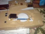
(The attached is very out of date but hopefully give a reasonable impression of size )
. Unfortunately my tank is a 1/35 scale Abrams so is a bit tiny. also, the price of the compass modules is quite high I recall.The only real issue with an accelerometer is getting one of a small size (that I can actual make a PCB for) and the fact that the tank is moving, which would corrupt readings of angles.
Anyway, I't too late for me to be able to think properly, so until tomorrow,
Thanks.
(The attached is very out of date but hopefully give a reasonable impression of size
)Attachments
-
 790.3 KB Views: 13
BeanieBots
Moderator
Glad to see you haven't given up. Keep at it.
Well, as discussed, a gyro is an accelerometer INCLUDING the electronics that you need to do the task you want, but we've been down path already so, up to you.
I agree with the others that excessive gain is likely to be the cause of your oscillations. However, the clue is in the word oscillation. It includes the time domain. I appreciate that you have limited space but in order to understand and hence solve your problem, you should build a rig on which you can try out different methods even if (for now) they could not be implemented.
Adjust the gain. Note how it effects both amplitude and frequency of the oscillations.
In particular, try to increase the angular inertia so that it matches closer to the amount the gyro was actually designed to control and fit the gyro slightly off centre from the turn moment.