GreenLeader
Senior Member
I am a Picaxe novice and an electronics beginner. I am planning to read a transducer with the 10bit ADC on a PICAXE (not sure yet which one) - any comments on my plan appreciated ")
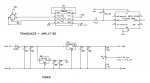
The transducer needs a 10V supply and outputs +/-225mV.
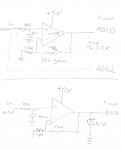
I intend to use an AD623 with gain of 10 and a Vref of 2.5V to give me 2500mV +/- 2250mV for the Picaxe 10bit ADC to read.
It is possible that the transducer can output say 400mV if it is overloaded. In this case the Picaxe ADC will see 2500+4000=6500mV.
My circuit diagram is attached - I have 3 questions:
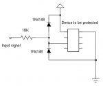
1. Will 6500mV on the ADC damage the Picaxe? If so how can I protect the Picaxe?
2. I am using a pair of resistors as a divider to provide Vref at 2500mV. Is this a satisfactory solution and what sort of magnitude resistors should I use?
3. Is my layout with two regulators and caps satisfactory? (LM78L05 for 5V to Picaxe and LM2904 for 10V to transducer, all powerd by a 12V battery).
Many thanks
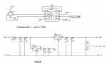
The transducer needs a 10V supply and outputs +/-225mV.
I intend to use an AD623 with gain of 10 and a Vref of 2.5V to give me 2500mV +/- 2250mV for the Picaxe 10bit ADC to read.
It is possible that the transducer can output say 400mV if it is overloaded. In this case the Picaxe ADC will see 2500+4000=6500mV.
My circuit diagram is attached - I have 3 questions:
1. Will 6500mV on the ADC damage the Picaxe? If so how can I protect the Picaxe?
2. I am using a pair of resistors as a divider to provide Vref at 2500mV. Is this a satisfactory solution and what sort of magnitude resistors should I use?
3. Is my layout with two regulators and caps satisfactory? (LM78L05 for 5V to Picaxe and LM2904 for 10V to transducer, all powerd by a 12V battery).
Many thanks
Attachments
-
 189.1 KB Views: 112