Programming Adafruit 4-Digit Displa7 (HT16K33)

elec_mech

New Member
Hi All,

Well, I'm at my wits end, so I thought I'd ask the experts. I'm attempting to use an Adafruit 4-digit display that uses an I2C IC, specifically the Holtek HT16K33. I haven't located any PICAXE code for this, but I've poured through the datasheet and attempted to reverse engineer the Arduino code written for it. Unfortunately, that is a painful experience.

I've come up with what I think is close below, but no dice. I can't get the display to show anything.

Code:
#picaxe 20m2				' Define PICAXE 20M2
#no_data					' Ignore EEPROM data - loads program faster

Initialize:					' Initial pins and set up variables
	LET dirsB = %11111111		' Make all B pins outputs
	LET dirsC = %00000011		' Make pins C.0 & C.1 outputs; rest as inputs
	LET pinsB = %00000000 		' Turn off all outputs on port B
	LET pinsC = %00000000 		' Turn off all outputs on port C
PAUSE 2000
Main:						' Main Routine
	i2cslave %11100000, i2cfast, i2cbyte			' Set slave address to DS1307
	writei2c 0, (%00100001) ' Turn on clock
	writei2c 0, (%10100000)	' Set all rows as outputs
	writei2c 0, (%11101111)	' Set brightness to maximum
	writei2c 0, (%10000000)	' Disable blinking and turn off display
	writei2c 0,($FF,%10000001)	' Set all rows high for column 1 (digit 1) followed by turn display on command - expect to see 8 on first digit of display
	PAUSE 1000		' Wait one second

END

Looking at page 32 of the datasheet, I think I'm starting things off right, but I'm not sure. The big question is whether I'm sending the actual data correctly. According to page 32, the bottom flowchart shows sending an address setting (I assume this is taken care of by the 0 right after the writei2c command signifying the address should be 0) followed by RAM data (not sure if I need to send one or two bytes) and finished with a display on command. Of course, maybe I'm sending the initialization commands wrong as well.

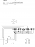
Also attached is a reversed engineered schematic since I couldn't find one online.

Any suggestions greatly appreciated. Will post final code if ever I figure this bugger out.
 

Attachments

  • Adafruit 4-Digit Display Schematic.png
    Adafruit 4-Digit Display Schematic.png
    333.3 KB · Views: 85
After a quick look at the datasheet, it looks like you should be specifying a location for your commands, like for starting the clock:
Code:
writei2c 0x20,(%00100001) ' Turn on clock

See page 30 of the datasheet for the locations and registers table.
 
Last edited:
I tried your suggestion and still no dice.

Code:
Main:						' Main Routine
	i2cslave %11100000, i2cfast, i2cbyte			' Set slave address to DS1307
	writei2c 0x21, (%00100001) ' Turn on clock
	writei2c 0xA0, (%10100000)	' Set all rows as outputs
	writei2c 0xEF, (%11101111)	' Set brightness to maximum
	writei2c 0x80, (%10000000)	' Disable blinking and turn off display
	writei2c 0,($FF,$FF, %10000001)	' Set all rows high for column 1 (digit 1) followed by turn display on command - expect to see 8 on first digit of display
	PAUSE 1000		' Wait one second

END

It seems a little counter-intuitive only because, if I'm understanding correctly, I'm sending the command byte twice.

As an aside, I've checked power to the board (5VDC from USB programmer) and that B.7 is connected to the clock line and B.5 is connected to the data line. A2-A0 in the schematic are unconnected, so according to the data sheet, the slave address should be %11100000 if I follow it correctly.

I think the key to this is on page 28 and 32, but I just don't understand how to carry out the write operation and how the PICAXE sends I2C commands.

According to page 28 of the data sheet, write operations must send the slave address followed by the command or address byte. I'm assuming that by defining the slave address in i2cslave as %11100000, the PICAXE will send this byte first every time a writei2c command is sent. Is this correct?

Example, if I write this:
Code:
	i2cslave %11100000, i2cfast, i2cbyte			' Set slave address to DS1307
	writei2c 0, (%00100001) ' Turn on clock

Then the PICAXE will send: %11100000, 0x00, %00100001, although that doesn't seem to follow the format on page 28.

Or, should I call out the slave address in the location variable of writei2c then send the command byte in the variable section?

Example:

Code:
writei2c %11100000, (%00100001)    ' Turn on clock

I just tried a few iterations without success. Ugh.

I'm also confused by the commands being listed as D15-D8. Does that mean I need to send a zero byte (0x00) after every command and/or that I need to use i2cword instead of i2cbyte? Looking at the read structure on page 29, I'm guessing not.

I think I can group my problems into groups:
1) How to send the proper write command.
2) How to send the proper command to change the row output values.

Latest attempt:
Code:
Main:						' Main Routine
	i2cslave %11100000, i2cfast, i2cbyte			' Set slave address to DS1307
	pause 100
	writei2c %11100000, (%00100001) ' Turn on clock
	pause 100
	writei2c %11100000, (%10100000)	' Set all rows as outputs
	pause 100
	writei2c %11100000, (%11101111)	' Set brightness to maximum
	pause 100
	writei2c %11100000, (%10000000)	' Disable blinking and turn off display
	pause 100
	writei2c %11100000,(0x00, $FF)	' Set all rows high for column 1 (digit 1) followed by turn display on command - expect to see 8 on first digit of display
	PAUSE 1000		' Wait one second

END

Sorry for all the questions, this data sheet just doesn't seem very clear.
 
I translated the Bus Pirate commands to Picaxe code as best I could.

Code:
i2cslave %11100000, i2cfast, i2cbyte

writei2c (0x21) 	' Turn on clock
pause 100
writei2c (0xEF)	' Set brightness to maximum
pause 100
writei2c (0x81)	'turn blink off and display on
pause 100
writei2c (0x00, 0x06, 0xff, 0x5b, 0xff, 0x00, 0x00, 0x4f, 0xff, 0x66)	'Now, display "1 2 3 4"

end

I edited the program to remove the address from the i2c data in the program snippet.

Good luck,
Rick
 
Last edited:
See PICAXE Manual 2 page 75 and then try in the format :

Code:
Hi2cSETUP  %11100000, i2cfast, i2cbyte
PAUSE 1 ; [b]wait 1 ms for the display chip to initialise[/b]
Hi2cOUT ($21) ; start clock
Hi2cOUT ($A0) ; set all rows on
Hi2cOUT ($81) ; turn on the display
etc
etc
 
Wow, I was about to write I had no luck trying the pirate bus method but then I saw the other responses and tried Rick100's code and added an i2csetup. Success!

Here is some working code for anyone interested:

Code:
#picaxe 20m2				' Define PICAXE 20M2
#no_data					' Ignore EEPROM data - loads program faster

Initialize:					' Initial pins and set up variables
	LET dirsB = %11111111		' Make all B pins outputs
	LET dirsC = %00000011		' Make pins C.0 & C.1 outputs; rest as inputs
	LET pinsB = %00000000 		' Turn off all outputs on port B
	LET pinsC = %00000000 		' Turn off all outputs on port C
Main:
	i2cslave %11100000, i2cfast, i2cbyte
writei2c (0x21) 	' Turn on clock
pause 100
writei2c (0xEF)	' Set brightness to maximum
pause 100
writei2c (0x81)	'turn blink off and display on
pause 100
writei2c (0x00, 0x06, 0xff, 0x5b, 0xff, 0x00, 0x00, 0x4f, 0xff, 0x66)	'Now, display "1 2 3 4"

end

I never thought to not include the location variable in the writei2c command, but that appears to be what the problem was.

Before I forget, thank you everyone for your help and advice - I didn't think a solution would present itself so soon. Also thanks to everyone writing a bit of code to try - I help out on a beginner electronics forum and it's those details that really help.

westaust55, I got your code to work as well with a slight additional of i2cmaster to the first line. Here is that code:

Code:
#picaxe 20m2				' Define PICAXE 20M2
#no_data					' Ignore EEPROM data - loads program faster

Initialize:					' Initial pins and set up variables
	LET dirsB = %11111111		' Make all B pins outputs
	LET dirsC = %00000011		' Make pins C.0 & C.1 outputs; rest as inputs
	LET pinsB = %00000000 		' Turn off all outputs on port B
	LET pinsC = %00000000 		' Turn off all outputs on port C
Main:
Hi2cSETUP  i2cmaster,%11100000, i2cfast, i2cbyte
PAUSE 1 ; wait 1 ms for the display chip to initialise
Hi2cOUT ($21) ; start clock
Hi2cOUT ($A0) ; set all rows on
Hi2cOUT ($80) ; turn off the display
PAUSE 2000
Hi2cOUT ($81) ; turn on the display
Hi2cOUT (0x00, 0x06, 0xff, 0x5b, 0xff, 0x00, 0x00, 0x4f, 0xff, 0x66)
end

I turned the display on and off to verify operation after trying Rick100's code.

Thank you again everyone!
 
Glad to hear you got it working. Here is the discussion on the Adafruit forums referred to in the pevious link:
http://forums.adafruit.com/viewtopic.php?f=47&t=29897
The post by High Fidelity describes the layout of the display and how to address it. From reading his description, I think the first 0x00 in the line:
Code:
writei2c (0x00, 0x06, 0xff, 0x5b, 0xff, 0x00, 0x00, 0x4f, 0xff, 0x66)	'Now, display "1 2 3 4"

is the address for the display data. So this might be the proper way to write the line:
Code:
writei2c 0x00,(0x06, 0xff, 0x5b, 0xff, 0x00, 0x00, 0x4f, 0xff, 0x66)	'Now, display "1 2 3 4"

I would also follow westaust55 advice about using the newer hi2c commands. I thought about buying one of these displays a few months ago but was scared off when I saw the Arduino library.

Good luck,
Rick
 
Likewise good to see that you have the display now working.

Sorry about missing the i2cmaster parameter in my example :(

As the display controller datasheet emphasises a 1 ms delay form power on to allow the chip to initialise it would be good practive to just include such a short pause to be on the safe side.

The fact that the code you have now posted has a PICAXE initialisation with 4 LET assignment statements, at 4 MHz clock speed these equate to about 1 ms and may suffice but if you clearly include a
PAUSE 1 ; let display chip initialise before first access
then it is clear why the short delay is there.
 
How do I modify this (westaust55 based) code to work with a 20X2? I've changed it as below but I'm not getting any display. I have 4K7 pullups on SCL and SDA and my 'scope shows good signals on both.

Code:
#picaxe 20X2				' Define PICAXE 20X2
#no_data                                           ' Ignore EEPROM data - loads program faster

Initialize:					        ' Initialize pins and set up variables - do I need to do this?
	LET dirsB = %11111111		' Make all B pins outputs
	LET dirsC = %00000011		' Make pins C.0 & C.1 outputs; rest as inputs
	LET pinsB = %00000000 		' Turn off all outputs on port B
	LET pinsC = %00000000 		' Turn off all outputs on port C
Main:
	i2cslave %11100000, i2cfast_8, i2cbyte
writei2c (0x21) 	' Turn on clock
pause 100
writei2c (0xEF)	' Set brightness to maximum
pause 100
writei2c (0x81)	'turn blink off and display on
pause 100
writei2c (0x00, 0x06, 0xff, 0x5b, 0xff, 0x00, 0x00, 0x4f, 0xff, 0x66)	'Now, display "1 2 3 4"

end
 
How do I modify this (westaust55 based) code to work with a 20X2?

I2C commands are one of those things which, if working on one PICAXE, should also work on any other without any change. Some commands have been deprecated but those will still work -

I2cSlave -> HI2cSetup I2C_MASTER
WriteI2c -> HI2cOut

You could try changing the I2CFAST_8 to I2CSLOW in case the bus is running too fast for the chip to keep up. Otherwise it seems it may be a hardware issue. Double-check you have not got SDA and SCK crossed-over.
 
Checked Vcc/Gnd/SDA/SCK at the pins of the chip, all OK. Tried I2CFAST_8, I2CSLOW_8, I2CFAST, I2CSLOW. The boards are supposed to be 100% tested by Adafruit. Code posted above is stated to work. Very frustrating...
 
Got it working, my fault, set the wrong address on the board :o

I found some helpful picaxe code for the Adafruit/HT16K33 code on a German picaxe distributor site's forum here.
 
HT16K33 notes

Just found some of my old notes on the HT16K33. Not from a Picaxe project (looks like 8052-BASIC), but the notes do discuss some of the quirks of the gadget, (Note the comment on SETUP regs) so might be of some use for you.
I have used the HT16K33 with Picaxe chips before, but couldn't find the old code. With Picaxe, I most always use the OLED display (cause it's easy & I'm lazy).

For-what-it's worth dept:
I really wish the Picaxe folks would adopt the old 8052-BASIC chip for those times when we need floating point & arrays. The 8052 has been around for years (often found as a plug-in board on American PLCs). It's also easy to drop in & out of assembly language when microsecond timing resolution is needed. However, in most applications the Picaxe is a quicker solution because of the simple hardware design & nice editor.
 

Attachments

Thanks for posting that listing. Now I have had some experience I find it's actually a pretty easy to use part.
 
I bought a couple of 8x8 LED matrices that use the same i2c Adafruit backpack with the HT16K33 chip. It took me a while to figure out how to turn on the correct pixels in the matrix as there are a couple of "gotchas" due to the way the LED matrix is wired.
8x8 matrix LED.jpg

1. After initialising, the starting address ($00) is sent, then (in brackets in the example below), the string of data containing the value for each of the 8 columns, where the "value" is the row value in binary, MSB first. However, the row value is a 16 bit value and only the first 8 bits are physically connected. So, every other byte is ignored. I have put $AA into each of these in the example below, just so they are not confused with anything else.
2. For some reason, the physical row 0 (at the top if you look at the display with the Adafruit logo at the bottom) is wired as the MSB so all the other rows are shifted down.

I know that is not a very good explanation but maybe the code will be helpful if anyone else has some of these.
Code:
#picaxe 08m2	' Define PICAXE 08M2
#no_data		' Ignore EEPROM data - loads program faster

Initialise:				' Initialise pins and set up variables
LET dirsC = %00000110		' Make pins C.1 & C.2 outputs; rest as inputs
LET pinsC = %00000000 		' Turn off all outputs on port C
Hi2cSETUP  i2cmaster,%11100000, i2cfast, i2cbyte
PAUSE 1 ; wait 1 ms for the display chip to initialise
Hi2cOUT ($21) ; start clock/oscillator
' $00 turns off the whole row

Main:
Hi2cOUT ($80) ; clear the display


' turn on all LEDS in each column (%11111111=$FF)
' x = don't care (not connected) but I have used $AA
'    start !  col0 x  , col1 x  , col2 x  , col3 x  , col4 x , col5 x  'col6 x  , col 7 x
Hi2cOUT $00, ($FF, $AA, $FF, $AA, $FF, $AA, $FF, $AA, $FF,$AA, $FF, $AA, $FF,$AA, $FF, $AA) 
Hi2cOUT ($81) ; turn on the display
pause 1000

' now draw a smiley face
'  xxxx  
' x    x
'x x  x x
'x      x
'x x  x x
'x  xx  x
' x    x
'  xxxx


'    columns
'7 6 5 4 3 2 1 0
'0 0 1 1 1 1 0 0 row0
'0 1 0 0 0 0 1 0 row1
'1 0 1 0 0 1 0 1 row2
'1 0 0 0 0 0 0 1 row3
'1 0 1 0 0 1 0 1 row4
'1 0 0 1 1 0 0 1 row5
'0 1 0 0 0 0 1 0 row6
'0 0 1 1 1 1 0 0 row7

'Adafruit logo at bottom

'MOVE TOP ROW (ROW0) TO bottom (MSB) AND SHIFT EVERYTHING ELSE DOWN=>BIT0->BIT7, BIT7->BIT6, BIT6->BIT5

' becomes....

'    columns
'7 6 5 4 3 2 1 0
'0 1 0 0 0 0 1 0 row0
'1 0 1 0 0 1 0 1 row1
'1 0 0 0 0 0 0 1 row2
'1 0 1 0 0 1 0 1 row3
'1 0 0 1 1 0 0 1 row4
'0 1 0 0 0 0 1 0 row5
'0 0 1 1 1 1 0 0 row6
'0 0 1 1 1 1 0 0 row7

'Adafruit logo at bottom

'for example, after shifting row 0, column 0 becomes %00011110 or $1E
'    start !  col0 x  , col1 x  , col2 x  , col3 x  , col4 x , col5 x  'col6 x  , col 7 x
Hi2cOUT $00, ($1E, $AA,$21, $AA, $CA, $AA, $D0, $AA, $D0,$AA, $CA, $AA, $21,$AA, $1E, $AA)
Hi2cOUT ($81) ; turn on the display
pause 1000

Hi2cOUT ($E0) 'dim the display (range $E0 to $EF)
pause 1000
Hi2cOUT ($EF) ' full brightness again
pause 1000
Hi2cOUT ($83) 'blink the display ($83=2Hz blink, $85=1Hz, $87=0.5Hz)
pause 3000
Hi2cOUT ($80) ; turn off the display
pause 1000
goto main
 
Hello Guru's, it's been a while. Hope you are all well in these crazy times.

Here I am resurrecting yet another quite old thread...

I am currently toying with the HT16K33's. I have it functioning relatively fine, however, I can't work out how to toggle/change the state of a single output without affecting an entire ROW.

The code below works fine to communicate with the chip, setup the parameters and at the end toggle the 4th bit ON with all other bits OFF, then turn ALL bits OFF. Fifty times. The 4th bit of $01 is COM 0/ROW 12 reference to the datasheet, I just randomly picked an output for this example. The PICAXE in use in this case is a 20X2.

The question is... How do I toggle just a single bit rather than essentially altering the state of all 8 bits which obviously affects the entire ROW?

HT16K33 Datasheet

Code:
init:
b0=0
b1=1   'Brief delay between I2C commands
w2=500

pause b1

main:

HI2cSetup I2CMASTER, $E0, I2CFAST, I2CBYTE    'HT16K33 I2C Address is $E0 with A0, A1, A2 left Open.

hi2cout ($21)    'Turn on Oscillator

pause b1

hi2cout ($A3)    'Set ROW15/INT pin HIGH when any button is been pressed

pause b1

hi2cout ($EF)    'Max Brightness

pause b1

hi2cout $00,(b0)    'SET ROW 0-7, COM 0        *** Set ALL LED's to OFF state.

pause b1

hi2cout $01,(b0)    'SET ROW 8-15, COM 0

pause b1

hi2cout $02,(b0)    'SET ROW 0-7, COM 1

pause b1

hi2cout $03,(b0)    'SET ROW 8-15, COM 1

pause b1

hi2cout $04,(b0)    'SET ROW 0-7, COM 2

pause b1

hi2cout $05,(b0)    'SET ROW 8-15, COM 2

pause b1

hi2cout $06,(b0)    'SET ROW 0-7, COM 3

pause b1

hi2cout $07,(b0)    'SET ROW 8-15, COM 3

pause b1

hi2cout $08,(b0)    'SET ROW 0-7, COM 4

pause b1

hi2cout $09,(b0)    'SET ROW 8-15, COM 4

pause b1

hi2cout $0A,(b0)    'SET ROW 0-7, COM 5

pause b1

hi2cout $0B,(b0)    'SET ROW 8-15, COM 5

pause b1

hi2cout $0C,(b0)    'SET ROW 0-7, COM 6

pause b1

hi2cout $0D,(b0)    'SET ROW 8-15, COM 6

pause b1

hi2cout $0E,(b0)    'SET ROW 0-7, COM 7

pause b1

hi2cout $0F,(b0)    'SET ROW 8-15, COM 7

pause b1

hi2cout ($81)    'Turn ON Display

pause b1


'******** Toggle bit 4 ON/OFF ********
for b0=1 to 50

hi2cout $01,($10)

pause w2

hi2cout $01,($00)

pause w2

next
'************************************

What am I missing O WISE ones of PICAXE land???


Regards,
Mort.
 
Instead of using $10 and $00 send a variable, say b5, which has a copy of all 8 bits.

You can the use setbit/clearbit on b5 to change each bit one-by-one as necessary. Because you have a local 'copy' saved in b5, when you send b5 it will still keep the other 7 bits in the same state.
 
Instead of using $10 and $00 send a variable, say b5, which has a copy of all 8 bits.

You can the use setbit/clearbit on b5 to change each bit one-by-one as necessary. Because you have a local 'copy' saved in b5, when you send b5 it will still keep the other 7 bits in the same state.

Thanks for that. Yep, I can see that will semi achieve what I am after, however reading the datasheet (page 10) they talk about 'Display Data Address Pointer. I am thinking this is what I am after, but just how to directly alter a single bit by command?


Regards,
Mort.
 
For the sake of the forum Technical's post #18 is the only way this can be achieved. Noted from Holtek themselves.


Regards,
Mort.
 
For anyone still struggling with this display and controller. I have sorted the all of the addresses out. Please see the program listing below. Please let me know if I missed something or if something is not clear?

' using 20X2 with hardware i2c on Pins b.7 (CLK) and pin b.5 (SDA)

' HT16K33 $E0 // I2C bus address for Ht16K33 backpack - default address with A0, A1, and A2 un-soldered
' HT16K33_ON $21 // turn device oscillator on
' HT16K33_STANDBY $20 // turn device oscillator off
' HT16K33_DISPLAY ON $81 // turn on output pins - no blinking
' HT16K33_DISPLAY OFF $80 // turn off output pins
' HT16K33_BLINK ON $85 // blink rate 1 Hz ($83 for 2HZ, 85 for 1HZ, 87 for .5HZ)
' HT16K33_BLINK OFF $81 // same as display on
' HT16K33_Brightness 0$EF // Max brightness
' Digit address $00 is the left digit, $02 second digit from left, $04 all dots (see below), $06 third digit from left, $08 last dight on the right
' Digit patterns
' $3F = 0
' $06 = 1
' $5B = 2
' $4F = 3
' $66 = 4
' $6D = 5
' $7D = 6
' $07 = 7
' $7F = 8
' $6F = 9
' $77 = A
' $7C = b
' $39 = C
' $5E = d
' $79 = E
' $71 = F

'To control the colon and decimal points, use the data shown below at address $04 for individual colon dots (Note that both dots of the center colon are wired together internal to the display's it is not possible to address them separately.) $1E turns all of the dots at address $04.

' $02 - center colon (both dots) (0000 0010)
' $04 - left colon - upper dot (0000 0100)
' $08 - left colon - lower dot (0000 1000)
' $10 - decimal point (upper right) (0001 0000)

init:
#no_data
#no_table

b1=1 'Brief delay between I2C commands


pause b1

main:

Pause 1500 ' not needed - I used it give me time to start my logic analyzer to capture the I2C traffic

HI2cSetup I2CMASTER, $E0, i2cfast_8, I2CBYTE 'HT16K33 I2C Address is $E0 with A0, A1, A2 left Open.

hi2cout ($21) 'Turn on Oscillator

pause b1

hi2cout ($EF) 'Max Brightness

pause b1

hi2cout ($81) ' turn display on

pause b1

hi2cout ($00, $06, $02, $5b, $04, $02, $06, $4f, $08, $66) ' now display 1234 and center colon only

pause b1

goto main
 
Last edited:
Back
Top