I’m wondering if anyone else has used a TLE5206 H-Bridge recently and what is their experience with them. I first bought 4 of these from China back in 2012 and found them very useful. One was used in a model train with PWM for forward and backward motor control and another to drive an electric drill to raise and lower a chook door. Both are still working flawlessly. I bought another 4 in 2013 again from China to use as spares for later.
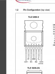
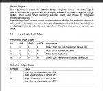
Recently, I was building a very simple power supply which was to use an 08M2 and the TLE5206 H-Bridge but the H-Bridge didn’t behave as expected and appeared to cause problems to the USB to Serial RS232 cable device (also from China) when programming the 08m2. The software kept losing the device and the USB had to be taken out and reinserted to get recognised again. Eventually, it failed completely and couldn’t be recognised. The output from the H-Bridge was also erratic and output 1 (pin 1) would go high when both inputs 1 & 2 (pins 3 & 5) were low but would go low with any other combination of inputs. In fact, with both inputs high, both outputs were low although output 1 did rise to a couple of volts. Output 2 (pin 7) appeared to operate normally and follow input 2 (pin5) as long as input 1 (pin 3) was kept low.
Summarising
(apologies about the formatting. I don't know how to improve it)
I assumed that I’d somehow destroyed the TLE5206 H-Bridge by inadvertently touching something that I shouldn’t so I replaced it only to find the circuit still behaved exactly as before. I again suspected that it was something I’d done and made some blunder with my circuit board but careful inspection of it didn’t reveal anything.
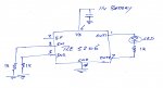
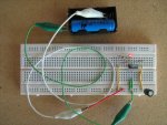
I then made up a very simple circuit with an 11 volt battery supply (3 Li-ion batteries) to pins 6 & 4 (also with a 220uF capacitor across them) and with both inputs grounded with a 1k resistor. I placed a LED & 1k resistor across the outputs and as you can see from the picture, the LED lit up when both outputs should be low.
I got exactly the same result from every other TLE5206 that I had. I then ordered another 6 TLE5206’s from a different supplier in China which have just arrived and they are all showing this same odd behaviour.
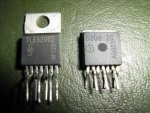
It seems extremely unlikely to me that of the 14 devices that I’ve now purchased from 2 different suppliers (and also the latest 6 are the 2S version of the device while the earlier 8 were the 2G version), the first 3 (picked at random) worked perfectly but all the remaining ones are flawed in the same way.
If anyone can see that I’m doing something stupid or I’m overlooking something obvious, please let me know as I’ve now spent a considerable amount of time checking this out. Also if anyone has purchased any of these recently and they are working as expected, then please let me know your supplier.
Recently, I was building a very simple power supply which was to use an 08M2 and the TLE5206 H-Bridge but the H-Bridge didn’t behave as expected and appeared to cause problems to the USB to Serial RS232 cable device (also from China) when programming the 08m2. The software kept losing the device and the USB had to be taken out and reinserted to get recognised again. Eventually, it failed completely and couldn’t be recognised. The output from the H-Bridge was also erratic and output 1 (pin 1) would go high when both inputs 1 & 2 (pins 3 & 5) were low but would go low with any other combination of inputs. In fact, with both inputs high, both outputs were low although output 1 did rise to a couple of volts. Output 2 (pin 7) appeared to operate normally and follow input 2 (pin5) as long as input 1 (pin 3) was kept low.
Summarising
Code:
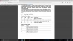
    Input       Output
pin3	pin5	pin1	pin7
 L       L       H      L
 L       H       L      H
 H       L       L      L
H H 2.14v 0.5vI assumed that I’d somehow destroyed the TLE5206 H-Bridge by inadvertently touching something that I shouldn’t so I replaced it only to find the circuit still behaved exactly as before. I again suspected that it was something I’d done and made some blunder with my circuit board but careful inspection of it didn’t reveal anything.
I then made up a very simple circuit with an 11 volt battery supply (3 Li-ion batteries) to pins 6 & 4 (also with a 220uF capacitor across them) and with both inputs grounded with a 1k resistor. I placed a LED & 1k resistor across the outputs and as you can see from the picture, the LED lit up when both outputs should be low.
I got exactly the same result from every other TLE5206 that I had. I then ordered another 6 TLE5206’s from a different supplier in China which have just arrived and they are all showing this same odd behaviour.
It seems extremely unlikely to me that of the 14 devices that I’ve now purchased from 2 different suppliers (and also the latest 6 are the 2S version of the device while the earlier 8 were the 2G version), the first 3 (picked at random) worked perfectly but all the remaining ones are flawed in the same way.
If anyone can see that I’m doing something stupid or I’m overlooking something obvious, please let me know as I’ve now spent a considerable amount of time checking this out. Also if anyone has purchased any of these recently and they are working as expected, then please let me know your supplier.
Last edited by a moderator: