Hi,
Recently, I've been developing a "Serial to I2C" converter in an 08M2. One application would be to emulate an AXE132, but to drive an LCD carrying one of the "I2C expander" backpacks. The PIC(axe)'s hardware serial UART and an interrupt are used to give adequate speed and reliability. However, this has proved to be a considerable "can of worms":
Firstly, HSERIN uses the same pin as I2C SDA and I've no wish to write (or use) bit-banging I2C code. Fortunately, the "base" PIC has an Alternate Pin Function (APFSEL) SFR which allows the HSER input to be swapped onto Port C.5. That's not ideal (because it's the Serial Programming input) but beggars can't be choosers.
Next, Microchip "forgot" to include a programmable exclusive-or gate on the serial input hardware, so it only works with "TTL" polarity (idle high) whilst PICaxe needs idle-low for programming the chip. For some applications the source could generate "T" data, or alternatively the PICaxe's on-chip "Data Signal Modulator" includes EXOR/Inverter gates which can be arranged to invert the serial data polarity. But both these methods require a "switch" (or pin links) to convert the PICaxe from Programming to Application mode.
Therefore, I devised a simple one-transistor (plus two 100k resistors) inverter stage to permit the PICaxe to automatically switch from Programming mode (at power-up/reset) to normal Running mode. A "hippy-style" schematic diagram is shown at the foot of the Program listing below. If pin C.4 is set as an input (or high) then the NPN transistor is OFF and the normal PICaxe data is passed to the input pin (via the 100k resistor). But if the emitter (C.4) is pulled Low, with a "Weak Pullup" resistor applied to the collector (C.5), then the signal to the PICaxe serial input becomes inverted. Unfortuantely, the PICaxe Editor doesn't support a pullup on the serial input, but the on-chip hardware can be enabled with a SFR command (POKESFR WPUA,32).
Next, it's necessary to generate an interrupt to read the tiny (two-byte) serial input buffer, but C.5 is not a valid interrupt input (why?). So it appears necessary to link C.5 to C.3 (the only remaining spare pin), which does allow a PULLUP to be used (although some might prefer to activate the pullups on both pins with a POKESFR $8C.40).
So finally, I could write a test program (similar to below) to "echo" characters, using a 16 MHz clock and 4800 baud. This worked well for single (i.e. spaced) characters, but even the second character was usually corrupted when concatenated with the first (i.e. using PE's terminal with the "5 ms delay" option cleared). Eventually, I tried using basic PEEKSFR commands (in place of HSERIN) and then all characters were echoed correctly. Is there a flaw in my use of HSERIN in the program?
The program below allows the two versions to be compared, by defining (or not) the "USE_HSERIN" parameter. Theoretically, HSERIN should be better because it can read the input byte immediately, whilst the SFR code must test the buffer flag before reading the byte. However, in practice, the interrupt seems more than fast enough, such that it's usually necessary to read the status flag several times before the byte is fully received into the buffer (the interrupt is generated by the leading edge of the start pulse). Other features of the test program are that it transmits a "tick" (=) every two seconds to show that the main loop is still running, and after a minute it restores the Programming input and reports the number of bytes received (as a check if some characters were not echoed).
The SFR version even "almost works" at 9600 baud, receiving about 5 concatenated bytes correctly (depending on the exact program staructure) before "locking up". This seems to be due to the "Overrun" hardware flag becoming set; the easiest method I've found to reset it (before any more bytes can be received) is to issue another HSERSETUP command (followed by APFCON if appropriate). Conversely, the USE_HSERIN version doesn't seem to work even at 2400 baud. The SFR version does, although it occasionally "holds onto" the echo for a few seconds (possibly because the interrupt is exited before the character has arrived).
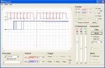
Generally, the interrupts in the test code occur during a PAUSE (so the response can be fast), but the following screenshot shows the interrupt entry (Marker in lower waveform) for pairs of concatenated characters when main: is running some real I2C control code. The upper waveform consists a Start Pulse, 7 "eyes" of ASCII data (32 - 127) then the msb (=0), Stop and Start levels, followed by a further 7 data-eyes, etc. However, it's difficult to test (at least using the PE terminal) the maximum latency for the situation where another character arrives just as the Return is being executed.
Cheers, Alan.
Recently, I've been developing a "Serial to I2C" converter in an 08M2. One application would be to emulate an AXE132, but to drive an LCD carrying one of the "I2C expander" backpacks. The PIC(axe)'s hardware serial UART and an interrupt are used to give adequate speed and reliability. However, this has proved to be a considerable "can of worms":
Firstly, HSERIN uses the same pin as I2C SDA and I've no wish to write (or use) bit-banging I2C code. Fortunately, the "base" PIC has an Alternate Pin Function (APFSEL) SFR which allows the HSER input to be swapped onto Port C.5. That's not ideal (because it's the Serial Programming input) but beggars can't be choosers.
Next, Microchip "forgot" to include a programmable exclusive-or gate on the serial input hardware, so it only works with "TTL" polarity (idle high) whilst PICaxe needs idle-low for programming the chip. For some applications the source could generate "T" data, or alternatively the PICaxe's on-chip "Data Signal Modulator" includes EXOR/Inverter gates which can be arranged to invert the serial data polarity. But both these methods require a "switch" (or pin links) to convert the PICaxe from Programming to Application mode.
Therefore, I devised a simple one-transistor (plus two 100k resistors) inverter stage to permit the PICaxe to automatically switch from Programming mode (at power-up/reset) to normal Running mode. A "hippy-style" schematic diagram is shown at the foot of the Program listing below. If pin C.4 is set as an input (or high) then the NPN transistor is OFF and the normal PICaxe data is passed to the input pin (via the 100k resistor). But if the emitter (C.4) is pulled Low, with a "Weak Pullup" resistor applied to the collector (C.5), then the signal to the PICaxe serial input becomes inverted. Unfortuantely, the PICaxe Editor doesn't support a pullup on the serial input, but the on-chip hardware can be enabled with a SFR command (POKESFR WPUA,32).
Next, it's necessary to generate an interrupt to read the tiny (two-byte) serial input buffer, but C.5 is not a valid interrupt input (why?). So it appears necessary to link C.5 to C.3 (the only remaining spare pin), which does allow a PULLUP to be used (although some might prefer to activate the pullups on both pins with a POKESFR $8C.40).
So finally, I could write a test program (similar to below) to "echo" characters, using a 16 MHz clock and 4800 baud. This worked well for single (i.e. spaced) characters, but even the second character was usually corrupted when concatenated with the first (i.e. using PE's terminal with the "5 ms delay" option cleared). Eventually, I tried using basic PEEKSFR commands (in place of HSERIN) and then all characters were echoed correctly. Is there a flaw in my use of HSERIN in the program?
The program below allows the two versions to be compared, by defining (or not) the "USE_HSERIN" parameter. Theoretically, HSERIN should be better because it can read the input byte immediately, whilst the SFR code must test the buffer flag before reading the byte. However, in practice, the interrupt seems more than fast enough, such that it's usually necessary to read the status flag several times before the byte is fully received into the buffer (the interrupt is generated by the leading edge of the start pulse). Other features of the test program are that it transmits a "tick" (=) every two seconds to show that the main loop is still running, and after a minute it restores the Programming input and reports the number of bytes received (as a check if some characters were not echoed).
Code:
; HSERIN TESTS using 08M2
; AllyCat October 2014

#picaxe 08m2
#no_data
;#define USE_HSERIN	; Selects Alternative buffer-reading code **

; EUSART:SFRs
symbol APFCON 	= $5D	; 128/0=RX on c.5/c.1; 8/0=T1G on c.3/c.4 ; 4/0 = TX on c.4/c.0
symbol BAUDCON	= $7F	; 8 = 16-bit Baud rate Generator (High byte at $7C)
symbol RCREG 	= $79	; Serial receive register
symbol TXREG 	= $7A	; Transmit byte register
symbol TXSTA 	= $7E	; 32 = TX Enable; 4 = High speed Baud rate; 2 = TRMT(RO) = Regiter is EMPTY
symbol RCSTA 	= $7D	; 128 = Ser Port Enable (RX & TX); 16 = Continuous Receive Enable **
symbol PIR1 	= $11	; RCIF = 32 = Received byte NOT yet read, 16 = TXIF = NO byte in buffer

symbol tempb 	= b20					; Temporary (local) variable
symbol timeout	= b21					; Timeout to check for more incoming bytes
symbol bytecnt = w13					; Number of bytes processed
symbol ptrin   = b22					; Input RAM Buffer Pointer
symbol ptrout  = b23					; Output RAM Buffer Pointer
symbol BUFST   = 64 					; Start address of hserial buffer
symbol BUFEND  = 127 				; Last address of hserial buffer
symbol MARKER  = c.2					; Unused pin to show when the interrupt is active
symbol BAUD 	= N4800_16			; Serial Baud rate
symbol HBAUD 	= B4800_16			; Hardware Serial Baude rate
;symbol BAUD 	= N9600_16			; )_Works for up to ~5 consecutive characters,then:
;symbol HBAUD 	= B9600_16			; ) receives no more until reset.

init:
#terminal 4800
	setfreq m16
	hsersetup HBAUD,2	; 16=Disable hserin;8=Disable hserout;2=INVERT SEROUT;4 & 1 must be 0
	pause 10
	pokesfr TXREG,"*"				; Mark if/when the Program (re-)starts
	pokesfr APFCON,128				; Move Hardware RX input to C.5
	disconnect						; Disable Program Downloader
	low c.4						; Enable the external inverter
	pullup %001000					; Pullup the SerIn/Interrupt pin (C.3)
	ptrin = BUFST					; Initialise the RAM serial buffer
	ptrout = BUFST
	pause 100
	hserin w0						; Flush the buffer
	setint 0,8						; Enable Interrupt on C.3 (active low)
	bytecnt = 0
main:
	do
		do while	 ptrin <> ptrout	; The RAM buffer is not empty
			peek ptrout,tempb
			pokesfr TXREG,tempb		; Transmit the byte
			inc ptrout
			if ptrout > BUFEND then	; Wrap buffer if overflow
				ptrout = BUFST
			endif
			do
				peeksfr TXSTA,tempb	; Test Transmit Buffer status
				tempb = tempb & 2
			loop until tempb = 2		; Repeat until buffer is empty
		loop
		pause 4000
		pokesfr TXREG,"="				; Report that the main loop is still alive
		pause 4000
	 		hsersetup HBAUD,2			; Recover from an overrun error (caused by too low clock rate)
			pokesfr APFCON,128		; Move Hardware RX input to C.5
	loop until time > 60			; Then restore the serial downloader
	setint off
	input c.4						; Disable inverter
	pullup 0						; Disable pullup
	pause 100
	reconnect
	hsersetup HBAUD,8					; 8=DISABLE HSEROUT; 2=Invert serout; 4 & 1 must be 0
	serout c.0,BAUD,(cr,lf,#bytecnt," bytes")		; Report the number of bytes processed
end

interrupt:
;	high MARKER					; Test marker   ***
#ifdef USE_HSERIN				; Appears NOT to work correctly
	w0 = -1 							; Set to a non-ASCII value
	hserin w0							; Request an input byte
	if b1 = 0 then						; A byte has been read into b0
reenter:
#else								; DOES seem to work well
	peeksfr PIR1,b0					; Read the Hardware Serial Status byte
	if bit5 = 1 then					; There is an Unread byte in the receive buffer
reenter:
		peeksfr RCREG,b0				; Read it
#endif
		poke ptrin,b0					; Store the received byte into RAM buffer
		inc ptrin
		if ptrin > BUFEND then		; Wrap buffer if overflow
			ptrin = BUFST
		endif
		inc bytecnt						; Total byte counter	for testing
		timeout = 0
		goto interrupt
	endif
	inc timeout								; Timeout counter
	if timeout < 4 then interrupt	; Don't exit too soon
	timeout = 0
#ifdef USE_HSERIN
	w0 = -1 								; Final check of the buffer before

exiting
	hserin w0						; Request an input byte
	if b1 = 0 then reenter			; A byte has been read into b0
#else
	peeksfr PIR1,b0				; Final check of the buffer before exiting
	if bit5 = 1 then reenter		; A byte has been received
#endif
	setint 0,8 					; Reset Interrupt input C.3 (active low)
;	low MARKER					; Test Marker for end of interrupt  ***
	return


#rem	; TEST HARDWARE SCHEMATIC:
Uses C.4 Low to Invert, C.3 for Interrupt input and Weak Pullup

                     +--------------*-----Vdd
                     |              |
SO----<--------------|-----------+ +++10uF
                     |  _______  | ===
                     | |o  U   | |  |
                     +-0-+  +--0-|--*-*---Vss
       100k            | /W |i | |   _|_
SI->-*-/\/\-*--------*-0 \P %n 0-+   ///
     |      |  NPN   | | /U |v |
     *---+  +-+  _+--|-0-|--+  0-<>-SCL )
     |   |     \ /!  | | %On   |        }-I2C
     \   |     ===   +-0-!     0-<>-SDA )
  10k/   | 100k |      |_______|
     \   +-/\/\-+        08M2
    _|_
///Generally, the interrupts in the test code occur during a PAUSE (so the response can be fast), but the following screenshot shows the interrupt entry (Marker in lower waveform) for pairs of concatenated characters when main: is running some real I2C control code. The upper waveform consists a Start Pulse, 7 "eyes" of ASCII data (32 - 127) then the msb (=0), Stop and Start levels, followed by a further 7 data-eyes, etc. However, it's difficult to test (at least using the PE terminal) the maximum latency for the situation where another character arrives just as the Return is being executed.
Cheers, Alan.