Problems programming a 40X2

Hi guys ... Stupid question time

Just got a new 40X2

never used a 40 pin one before or an X2 part so dont know if im missing anything.

i have all the required pins connected but ever time i download a program it find the chip and then comes back with:

ERROR:
Verification error - 0x00 transmitted but 0xFFFFFFF2 received at byte 0

What have i done wrong :(

Thanks

Alex
 

Andrew Cowan

Senior Member
What power supply are you using for the PICAXE? 3 AA batteries? Also, do you have decoupling/smoothing capacitors near the PICAXE's power pins?

A
 
Im using 3 AA batteries and have also tried USB power (What i use to run my other chips)

I dont have any capacitors anywhere.

Literally all i have is the download circuit, reset pin connected, power and 0V pins connected and resornator pins tied to ground

Cheers

Alex
 
Alex.
I assume that you've been successful before.

What are you using for your programming board?

e
I have been successful with then picaxe 08M, 28X, and 28X1's

I have it just on a simple breadboard at the moment for testing it works ... or not :p

Alex
 

eclectic

Moderator
Sorry for the mess :)

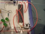
Im just soldering up a protyping board at the moment.

On the photos, ignore anything left of the LED'S and ignore the LED's too! :)
First quick response.
I'll lay money on the serial socket (bottom right)
NOT connecting correctly
with the breadboard.

Can you bodge a hard-wired connection?
And get some black wires for the grounds? :)

e
 

eclectic

Moderator
Secondly,
Manual 1, pages 8 and 38.

Build a minimal circuit.

Makes sure that

The two pairs of pins on the socket are connected (p.8)
and that both V+ and 0(gnd) are connected. (p.38)

Then add say a 100nF (0.1 micro F) V+ - gnd

e
 
Ok :)

Im just quickly knocking up a hard soldered version so i can eliminate any problems breadboard causes.

Be done in about 10 mins :D
 

hippy

Ex-Staff (retired)
Very likely download socket related. The pin order seems wrong also using the two outer-pins as if connected is a bad idea as they aren't connected once the jack is inserted.

The two XTAL connections to 0V - possibly doesn't matter but disconnect for now.

I would always recommend having three colours of wire, +V (red), 0V ( black) and everything else. Only put +V at the top of breadboard, only put 0V at the bottom.

Also, try to take the photograph directly from above to reduce parallax error, and put IC's in so pin 1 is on row 1.
 
Last edited:
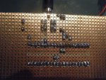
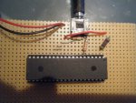
Ok the new board is done, all perfectly as should be, soldered well etc. Same error

I have noticed though the number on the pic chip is:

PIC18F45K22

Is this possibly the low power version and they have hence sent me the wrong one?

What are the XTAL connections ... never heard that terms before ?

:(

Alex
 
Hi guys

Here is the new board.

It doesnt have reset switch on it i know but this should affect nothing.

There are 2 cables under the picaxe connecting the powers to each side.

Sorry for the voltage rails and serial port on this one, i was getting them as close to the chip as possible to minimise voltage drop and noise.

Thanks all

Alex
 

Attachments

Hi guys !!!

Problem solved !

Well done tarzan :)

I was using linaxepad on ubuntu but it obviously doesnt support it yet.

Just switched back to windows, installed the new editor and it works perfectly!

Thanks ever so much guys!! :D

Alex

p.s. anyone know of any news on linux support for the programming editor ? apparently its in development :)
 
Top