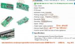
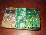
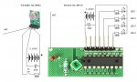
Problem with RF transmission

Pekari

Senior Member
Doesn't anyone have used these parts?

I modified receiver antenna to right length, but haven't found anywhere what transmitter antenna length should be so it's what it is.
 

Paix

Senior Member
Apparently not.

You say that you modified the receiver antenna to the right length, but haven't found anywhere what the transmitter antenna length should be - so how did you modify the RX antenna to the right length.

The length of the antenna for TX or RX is determined by the frequency of operation.

(300 / frequency in MHz) gives the wavelength / 4 gives the nominal length for a quarter wave antenna, in metres.

315MHz = 23.8cm
433MHz = 17.3cm

The length doesn't take account of the velocity factor of the antenna wire, which may end up being slightly shorter.

Make TX and RX antennas for the frequency in use, look over shoulder to make sure that neither SUPO or PVTK are listening to you. Prune the RX antenna 2mm at a time until the signal passes the peak (2mm of error is insignificant unless you want to stick it back on). Cut TX antenna to same length. You will also possibly need 1/4 wavelength ground plane raidals. I am assuming that the antenna is connected by a length of coaxial cable of some sort or other. Good Luck.

Snet at post #12 obviously has his crystal ball ticking over on standby then! Why pay more when others can pick up the tab :) Hmmmmmmm.
 

Pekari

Senior Member
Thanks, Paix!

In that case, here is wrong information of antenna! :(

Tomorrow I will modify antennas as such long you describe and test again.

I haven't buy anything from ebay, yet...
 

manuka

Senior Member
Their quoted "25mm" antenna length indeed seems incorrect by an order of magnitude! But look at the overall specs. Although it's quite sensitive & thankfully supply tolerant, it's VERY broadband & the cap. & coil look prone to misadjustment. Just what are all those pins for !?

IMNSHO it's not now really worth bothering with such cheapie super-regen receivers for data work, as superior superhet. types (Dorji ASK etc) abound for much the same prices- or less. Of course FSK offerings are usually better (as less prone to interference), & GFSK types- although more costly- are better still. Stan.
 

Attachments

srnet

Senior Member
The length of the antenna for TX or RX is determined by the frequency of operation.
Yes, and a 1/4 wave (39R ?) is about right if a module has a 50R output impedance or matching.

Note the 'if'

It may be that the quoted length is the correct length (impedance) for the output of the module. So unless we know for sure that it should be 50R, 1/4wave may well be the wrong length.

Also note that even with better modules the classic 1/4 wave may not be the best length, due to inaccuracies in components used for the impedance matching stages.

Trimming the antenna is the way to go, I have tested several of the RFM22s in this way, and in every case the classic 1/4 wave is the wrong length. The optimium in this case is around 10cm longer, some modules showing a more pronounced peak than others.
 

MPep

Senior Member
Yes, and a 1/4 wave (39R ?) is about right if a module has a 50R output impedance or matching.
A quarter wave is a quarter wave, no matter what the impedance of the aerial/antenna.
For transmitting, 50R is used for maximum power transfer from the transmitter to the aerial.
If using coaxial cable, then you also need to take the velocity factor into account.RG-58 has about 0.66 VF. This means that the 1/4wave through coax is only 2/3 than that of free space.

More info here.
 

Pekari

Senior Member
I don't use any coaxial cable with these. Just a wire to board.

Does R/C controlled cars and other work with any antennas in the little room area? These boards are death.
 

manuka

Senior Member
Sigh... In my experiences the antenna - bless it's heart- is often the last thing to worry about with these cheapie modules. Most work well across the room with just the bare connection! Far more crucial can be how you are driving it (both hardware & software wise), & local INTERFERENCE.

Please supply VERY full details, along with layout pictures etc. If you have a UHF scanner perhaps listen on that band segment for activity too. A "poor mans scanner" is handy for this. Stan
 

srnet

Senior Member
For transmitting, 50R is used for maximum power transfer from the transmitter to the aerial
Only if the output impedance of the transmitter is also 50R, it may not be ............

(and I do have a good understanding of cable velocity factor)
 
Last edited:

hippy

Technical Support
Staff member
Now I replaced antennas to about 258mm, still doesn't work.

How these modules should work?
Maybe they dont ?
Looking at the receiver datasheet in post #1 it indicates these are smart receivers which require an address match to activate their outputs which suggests they require a particular data packet format to be sent to make them work.

Is the correct data packet being sent ?
 
Last edited:

Pekari

Senior Member
hippy, aren't the transmitter input analog?
From some site I read these modules can use to send audio data easily.

With which code should I send? I haven't found code anywhere in the net.
 

manuka

Senior Member
Pekari: Hei -hei! Data sheets are usually non existent for cheapie offerings like this! My long standing experiences with such PICAXE driven ASK data modules indicate that most can be readily made to work in this manner. Check some sample coding here.

433 MHz super-regen. circuitry dates from more than a decade back (an eternity in electronics of course), & I again repeat that such receivers are now virtually obsolete for anything more than the likes of cheap short range wireless doorbells. You are really wasting your time (& ours) with them.

I again also repeat that you MUST supply your EXACT layout, circuitry, supply details, RF environment & PICAXE driving code if you want focused Forum help. We can NOT read you mind or view your workbench ...

Otherwise it's "over & out" from me- Stan.
 

Pekari

Senior Member
manuka:
Thanks. There is problem: This receiver send data via 4 pinout, so doesn't use serial bus.
Still I wrote code to transmitter, but any of LED:s doesn't light.

I have been asking a datasheets etc from supplier but have not been answered yet.
 

hippy

Technical Support
Staff member
Still I wrote code to transmitter, but any of LED:s doesn't light.
If you don't know what data to send; how do you know what you are sending is right, and how would anyone else tell if you have your code correct or not ?

You could post your source code and full circuit diagrams which would at least let people see what it is you are doing.
 

Goeytex

Senior Member
The receiver has an decoder on it. That would imply that the transmitter should have a matching encoder. It does not. Therefore this combination will never work.

@Pekari,

It seems to me that you have purchased cheap mismatched RF modules and are tying to make them do something that they cannot do.

You have not disclosed what you want to do with the RF modules. No one can help you unless you take the time to tell the forum "EXACTLY" what you are wanting to accomplish.
 
Last edited:

Pekari

Senior Member
hippy:
Code was from manukas post #16: sample coding here link.

But this transmitter is very simply circuit and I think it must be analog. These is no IC-brain. Only crystal and transistor (maybe) and 4 pin chip "RF19".

Goeytex:
Then WHY they have been selling these modules?

I need to send alarm data to ~200m area, data incluses an alarm code 0...127 in every 10 sec. Nothing else need to send.
 
Last edited:

Goeytex

Senior Member
Goeytex:
Then WHY they have been selling these modules?
Deal Extreme sells cheap surplus and old stock items usually without datasheets. That is their business - cheap leftovers that may or may not work.
When purchasing from places like Deal Extreme it is your responsibility to determine whether items are compatible. Just because the receiver and transmitter are the same frequency does not mean they are compatible.

The receiver you purchased has a decoder on it and is designed to operate 4 latched outputs. usually relays. A compatible transmitter will have a matching encoder that will accept 4 button presses to turn on/off the relays on the receiver side.

You are wasting your time (and ours) trying to get this combination to do anything. And now after several requests you still have refused to tell the forum what you wanting to accomplish. Unless you decide to tell us what you want to do, then no one can help you any further.

Good luck,
 

Pekari

Senior Member
Goeytex:
I have been answered.
Again: Need to send alarm code 0...127 in every 10 sec ~200m area. nothing else need to do.
Maybe I need to buy other transmitter-receiver pair to do this.

I hope we all can learn this something and I'm not only wasting your time but saving someones money too.
 

hippy

Technical Support
Staff member
As Goeytex explains; you have mismatch between transmitter and receiver. It's like shouting at a deaf person or showing pictures to a blind person to communicate - it simply won't work.

It may be possible to get the the transmitter to send what the receiver needs but that requires finding out what the receiver expects to receive then sending that. That's like needing to know what language a person understands because they will just stare blankly if a language they don't understand is used. Manuka's sample code doesn't speak the language your receiver understands. No one here currently knows what language the receiver does understand.
 

Pekari

Senior Member
THANKS, eclectic! I have been searching datasheets but haven't found any code like you do!
I have to check this out!
 

Goeytex

Senior Member
Receiver uses an SC2272 decoder. The transmitter will therefore need to use a PT2262 encoder.

Deal Extreme sells the 9902 Transmitter Module which 'should' be compatible.

However with no datasheet to give pinouts and code settings I think it would be rather difficult to get working. Even if you did, I think the range would not be more than about 50 meters and there would only be the possibility of 4 remote sensors for the alarm system.

There are much better choices than these cheap undocumented modules from DE. If you have adequate programming skills and good electronics understanding, the 20dBm HOPE RF RFM42B "front end " module might be a good choice. Dorji has a similar module that will use the exact same code in the DRF4432F20.
 
Last edited:

Pekari

Senior Member
I have getting forward on this!

I have modified receiver board and I take a analog signal straight from SC2272 input signal pin #14, DIN and I use code from manukas post #16.
 

Pekari

Senior Member
Yes!!!!!! I get it to send data!!!! Yes sir!!!

Thank you ALL!!!

I skip IC SC2272 and that's how it works now.

Not very length, only about 30 meters but maybe I need to modify antenna.
 
Last edited:

manuka

Senior Member
Pekari: Great! No doubt there's a Finnish saying relating to the English " Read the ****** instructions !" ...

A range of 30metres through wooden buildings & light vegetation is typical for these modules. You can usually increase range by 1/ Elevating the units above obstacles 2/ Using directive antenna (such as a "cotanga" approach) 3/ Lowering the data rate (to say 300 bps) or even 4/ Organising a repeater . You're in Nokia country so surely can -PLEASE- AT LEAST SEND PHOTOS OF YOUR CIRCUIT LAYOUT & TRANSMISSION PATH.

However -as repeatedly already mentioned- you seem to be trying "to make a silk purse from a sows ear" (English saying relating to using unsuitable raw materials for enhanced applications). Reliable links over several hundred metres require superior modules,probably with greater Tx power (25mW is normally legally allowed) & more sensitive receivers.

Stan. (New Zealand)
 

Pekari

Senior Member
manuka:
I haven't hear this saying.
Truth is: Last thing what typically finnish does is to read instructions!
Using old and recycling is my way to do many things.

Yesterday I install 2 transmitter to old (Made by me 2008 with PICAXE) wired receivers ~100m length wire under ground, so now working area is whole yard about 80x150m and is working well also inside of buildings.
I haven't builded a receiver yet, but I will make it pocket sizes with chargeable Li-ion battery.
There is a photos what is ready now:

Receiver+wireless transmitter 1.2.jpgReceiver+wireless transmitter 1.1.jpg
 

Pekari

Senior Member
More photos:
Receiver+wireless transmitter 2.3.jpgReceiver+wireless transmitter 2.1.jpg

I need to modify a transmitter to get it fit to this box.
My plan is to make pocket size alarm typically like this black.

Like you can see, only thing what can see outside is antenna wire. :)
 
Last edited:

Pekari

Senior Member
Now receiver hardware is ready.

Receiverboard.jpg

I removed IC SC2272-M4, it will not need in this project. There is not too much space!

Receiverin.jpg

I need to modify almost all components outside of circuit board. PICAXE programming connector was too BIG so I need to found smaller.
 

Pekari

Senior Member
Box is mobile phone desktop charger from dealextreme.

Controllable hardware features:
-ON/OFF switch
-button
-315MHz wireless receiver
-inbuild antenna
-7 red SMD LED
-2-color red/green LED in center
-piezo element, PWM-controllable
-readable battery voltage
-vibration motor
-chargeable Li-Ion battery (small Nokia charger plug)
-3,5mm connector to PICAXE programming.
-White LED (Flaslight)

Now I have to make working code to this... I have problems with input noise.


Receiver1.jpgReceiver2.jpg

My Nokia (C6-00) mobile phone is bigger than this!
 
Last edited:

Pekari

Senior Member
Some day it willl be more clear but some day can't read it property.
I have R-C-filtering but it's not sufficient. Bigger R-C filtering isn't answer, I have tryed it.

signal.jpg
 
Last edited:

Pekari

Senior Member
Yesterday I found many reason why I have problems with this.

- 2.transmitter power voltage too low
- wrong capacitor in R/C filtering. I was put smaller capacitor what I have used in test circuit!

View attachment 12124
- tiny SMD capacitor was disappeared from receiver circuit board (in the right hand side of the board) !

Receiver_broken.jpg


Now this device has beginning to work correctly!
 
Top