Problem with HP03 sensor

John O

Senior Member
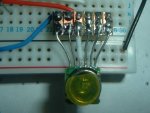
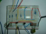
I've finally got my HP03 sensor from Futurlec but I'm having a bit of a problem with the reading it's returning.

I've followed WestAust55's tutorial here: http://www.picaxeforum.co.uk/showthread.php?t=14661 . I'm using the code shown in the tutorial verbatim with an 18M2. (I think the code has been updated to reflect changes to the sensor's register addresses).

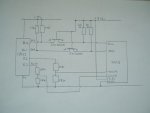
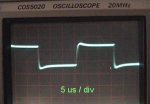
I've attached the circuit diagram I'm using. The 'scope seems to show the PWM is at the correct frequency (if I'm reading the scope correctly - maths again!).

The reading I'm getting back varies between 599.0 and 605.2

I can just about follow the code's I2C read/write operations but I'm not sure how to go about reading the 'compensation' values which are poked into the Picaxe.

Any pointers as to where I might start investigating would be appreciated :)

Thanks,

John.
 

Attachments

fernando_g

Senior Member
This is a comment more on the hardware than the software...

I see the level shifting what you are doing with the two Mosfets. However, I have an observation, which could cause some trouble.

When the Picaxe pulls down the B.1, B.4 pins, the body diode internal to the fets, will conduct and also pull down the SCL and SDA pins. However, the voltage drop across the body diode may cause the logic low on the SDA and SCL pins to be very close to Vil threshold----remember you are only running from 3.3 volts. An antiparallel schottky diode with each mosfet would alleviate the issue.

Maybe I'm overly concerned, but with the low cost of small signal schottkys I would still add them...they can't hurt.
 

John O

Senior Member
Thanks, I think those MOSFETS do have that diode. I just drew that quickly to post on the forum.

Sorry, I've just re-read your post - I'm feeling rather frustrated with Futurlec at the moment. [*]

I based the circuit using the MOSFETS on the Philips application note http://ics.nxp.com/support/documents/interface/pdf/an97055.pdf


[*] I'm beginning to suspect that I may have b**ggered the sensor soldering it to a header. Futurlec specifically advertise it as an HP03D, my invoice says HP03D but they eventually sent an HP03S. I very specifically ordered the 'D' because it's already on a header and suits my eyesight better.

In any event, a spare would be handy so I've just ordered an HP03D from here: https://www.oceancontrols.com.au/BPS-010.html


John.
 
Last edited:

fernando_g

Senior Member
Indeed, ALL Mosfets have an anti-parallel diode. It is called a body diode.
However since it is a parasitic element, both its static and switching characteristics are not good by any stretch of imagination.

Some Mosfet manufacturers specially process the devices to create good body diodes with proper characteristics. For instance, the Fetky family from IR.
A suitable schottky for your app would be a 1N5711, inexpensive and ubiquitous.
 

John O

Senior Member
Thanks. I'll get some on order. I take it, it just goes in parallel with the internal one?

The pressure sensor is the final piece of the weather station jigsaw so, as I posted above, I'm feeling a bit annoyed with Futurlec at the moment... I can't see any other reason for this thing not working other than I got it a bit hot when I soldered the header to it. After a 30 day wait for it to arrive, I didn't feel inclined to send it back but, if they feel it's ok to substitute parts, I'll think twice before I order from them again!
[/grumble]

:)

John.
 

westaust55

Moderator
@JohnO,

You circuit seems correct. The only difference of possible significane is that I have used 4.7 kOhm resistors for the i2c bus pull-up on both sides of the 2N7000 FET's instead of the 10 kOhm that your schematic shows.

Mine works perfectly well without added diodes across the FETs.

The higher value of pull up resistors means that it takes slightly longer for the ic2 data and clock signals to rise back from a low state to Vcc which can make a difference (all depends on parameters such as line capacitance).

In the 18X program that I had originally posted, the constants are read from the HP03S sensor and saved to EEPROM around lines 102 to 107.

Can you advise what values are being stored in PICAXE EEPROM from (decimal) locations 6 to 21.

Line 124 = READi2c (PMSB, PLSB)
is reading the pressure sensor data

Line 129 = READi2c (TMSB, TLSB)
is reading the temp sensor data

What values are you typically receiving for those?
 

John O

Senior Member
westaust55: First, my apologies for not replying sooner. This forum moves fast and the thread must have moved to page 2 or 3, so I completely missed your reply.

I've fired up the HP03 again this morning and the values do seem to be moving, just nowhere near what they should be.

Last week, it was returning around 600 when the actual pressure (according to nearby John Lennon Airport) was 1008. Today, it's reading around 590 and the actual pressure is 997. An error of around 408 each time.

I've temporarily added the following code at the end of the loop:
Code:
SERTXD ( #Pressur, ".", #Tenth, COM, CR, LF)
	read 6, b2, b3, b4, b5, b6, b7, b8, b9
	SERTXD ("6-13: ", #b2," ", #b3," ", #b4," ", #b5," ", #b6," ", #b7," ", #b8," ", #b9, CR, LF)
	read 14, b2, b3, b4, b5, b6, b7, b8, b9, b10, b11
	SERTXD ("14-23: ", #b2," ", #b3," ", #b4," ", #b5," ", #b6," ", #b7," ", #b8," ", #b9,  " ", #b10, " ", #b11,CR, LF)
	PEEK $54, WORD w2
	SERTXD ("Word $54 (Press): ", #w2, CR, LF)
	PEEK $56, WORD w2
	SERTXD ("Word $56 (Tempr): ", #w2, CR, LF)
     
	PAUSE 30000				; wait some time 60 seconds better  - reading to frequently warms [..]
	GOTO FetchNewData
and this is what's being returned:
Code:
589.8,
6-13: 214 76 94 12 61 1 15 3
14-23: 16 120 220 22 196 9 7 21 6 10
Word $54 (Press): 37996
Word $56 (Tempr): 29943
589.2,
6-13: 214 76 94 12 61 1 15 3
14-23: 16 120 220 22 196 9 7 21 6 10
Word $54 (Press): 37998
Word $56 (Tempr): 29934
Edit: I've just tried 4k7 pullups (first just on the HP03 side and then on both sides) but the results are exactly the same.


John.
 
Last edited:

westaust55

Moderator
Looking at a few of those data byte you have posted things seem incorrect at first glance.

For example calibration constant C2 is read from HP03 address 18:19 as MSB first and saved in PICAXE EEPROM locations 8 and 9 respectively.
Those values are 94 and 12 ==> 94*256 + 12 = 24076.
But the datasheet indicates the value should be in the range 0 to 8191.

If we considereds the first byte as LSB then 12*256 + 94 = 3166 which would be in range.

For C4 with MSB first we have 61*256 +1 = 1567 with is out of the range 0 to 350 yet if we swap the bits 1*256 + 61 = 317 which is in range.

Make me wonder if HOPERF have swapped the MSB and LSB bytes around in the EEPROM on the HP03S module. :confused:

That was the only checks I had time for tonight before heading out.

I was using Datasheet V1.3 dated 2010-2-3 which was the reference for my own earlier work and still available from the HOPERF website.

You could try swapping the order bytes for just the word bytes as stores to PICAXE EEPROM. That is for the first 7 pairs of sata and see if you get meaningful results.
Next step might be an Email to HOPERF seeking clarification/explanation
 

John O

Senior Member
Thanks for the observations.

I've swapped the bytes by reading them in the order they're stored instead of swapping the pairs as in your original code:
Code:
 SLAVEi2c PRE, i2cslow, i2cbyte	; set up to read the Pressure Sensor constants
      READi2c PreConst1,(b2, b3, b4, b5, b6, b7, b8, b9)	; read the first 8 values from the pressure module
      WRITE 6, b2, b3, b4, b5, b6, b7, b8, b9			; save the pressure constants in PICAXE EEPROM

      READi2c PreConst2,(b2, b3, b4, b5, b6, b7, b8, b9, b10, b11)  ; read the second 10 values from the pressure module
      WRITE 14, b2, b3, b4, b5, b6, b7, b8, b9, b10, b11
The result seems to be worse :(
Code:
5039.6,
6-13: 76 214 12 94 1 61 3 15
14-23: 120 16 22 220 9 196 7 21 6 10
Word $54 (Press): 37940
Word $56 (Tempr): 30063
Before I get in touch with HOPERF, I'll see what happens with the 'D' version that I've ordered from elsewhere.

Unfortunately, I struggled soldering the one Futurlec sent (the pads seem even smaller than in your photo, there being no pad area on the top surface at all). Although I seemed to solder it quite quickly, I may have damaged it.

John.
 

Attachments

Last edited:

John O

Senior Member
I emailed HopeRF and they replied promptly. Unfortunately, all they suggested at this stage is that I try another sensor or my code is wrong. I gave them a link to this thread so they could see that the code is correct.

They attached, as a pdf, the programming guide which I had already seen but isn't really any more helpful than the datasheet itself - for Picaxe. (What's the feasibility of someone writing a "Arduino/PIC/C -to- Picaxe" cross-compiler!)

http://www.hoperf.com/upfile/hp03_code.pdf

The reading seems to be consistently ~408 low according to the local airport.


Actual - HP03
1008 - 599
997 - 589
990 - 583


Those reading are with a fairly steady indoor temperature, which the final project will have anyway, so I suppose I could just add the 408.

When the jumbo-size HP03D arrives, that'll be the test!

John.
 

westaust55

Moderator
Prior to posting the final project for the HP03 barometric pressure sensor which you have already found, I have posted some information in this thread: http://www.picaxeforum.co.uk/showthread.php?t=13143

As you can see, I had a consistent albeit small difference of 3 hPa compared with the local weather station.

I will this evening look to try and locate the Excel spreadsheet that I had originally developed and post that here which may help you look for any anomalies in maths. Certianly the data you posted at first glace seemed out of spec relative to the datasheet.
 

eclectic

Moderator
Thanks.

Well, my new HP03D has arrived - this time from Ocean Controls. Unfortunately, they too don't seem to be able to tell the difference between an 'S' and a 'D'.

Perhaps it's me. Can someone else confirm that this link shows an HP03D complete with a 0.1" header: http://www.oceancontrols.com.au/search.php?mode=search&page=1

:mad:

John.
Yes it does.

And, remember posts 16/17 here
http://www.picaxeforum.co.uk/showthread.php?t=17597&page=2&highlight=funnels

Many a true word spoken..

e
 

John O

Senior Member
Many a true word spoken..

e
Absolutely - unfortunately at £130 a go, I could buy two complete weather stations from Maplins for that.

I've already spent at least that in the name of "fun" - which I don't mind; hobbies cost money, but it annoys me when companies don't send the items they advertise and cause me to waste money.... especially when we have to wait weeks and weeks for the things to arrive in the first place.

I'll end up just adding a 408 factor to the sensor I've got. I'll also build the MPX4115A with ADC chip and let them run side by side for a couple of weather "cycles" to see how they compare.

I've emailed Ocean Controls to tell them it's not what they advertised and to ask them what they want me to do with it! (I've got a few suggestions myself :) )

John.
 

westaust55

Moderator
Here (attached) is the Excel spreadsheet I worked on before committing to the PICAXE program maths.

change the file extension from .dsn to .xls
It may help you ascertain if there are math overflow issues if your calibration constants are significantly different from those in my couple of HP03S modules.
 

Attachments

John O

Senior Member
Thanks, I'll study the file and see if I can spot anything. As you noted, though, some of the constants I'm reading back are way outside the range specified in the datasheet.

I'll await a reply from Ocean Controls and if I get the impression they're not going to get particularly involved, I'll psych myself up and solder a header to this one!

John.
 

John O

Senior Member
I've had a very quick and helpful response from Ocean Controls. It seems they also get their stock from Futurlec and have been caught the same as me with the D and S models. They've already updated their website.

Ocean Controls have also very kindly offered to solder one to a small veroboad 'breakout' board for me.

Guess which company will get my future orders? :)

John.
 

John O

Senior Member
I know this is a very old thread but, now the weather station is finished, I've found a bit of time to have a play with the replacement HP03 sensor from Ocean Controls and tie up this thread :)

As they promised a replacement arrived shortly after my last post nicely soldered to a piece of stripboard complete with a 6-pin header.

The results below show the values of the various HP03 registers. First the old, suspect sensor and, second, the results from the new one.

Code:
605.5,
6-13: 214  76   [COLOR="Red"]94[/COLOR]  12   61   1   [COLOR="Red"]15[/COLOR]   3
14-23: [COLOR="Red"]16[/COLOR]  120  [COLOR="Red"]220[/COLOR]  22  196  9  7  21  6  10
Word $54 (Press): 38282
Word $56 (Tempr): 30479

1014.2,
6-13: 202  74  [COLOR="Red"]206[/COLOR]  13  60  1  [COLOR="Red"]187[/COLOR]  3
14-23: [COLOR="Red"]146[/COLOR]  121  [COLOR="Red"]95[/COLOR]  25  196  9  7  21  6  9
Word $54 (Press): 40269
Word $56 (Tempr): 30950
Thanks again to WestAust55 for your help. I think I can feel a small Altimeter project coming on :)

John.
 
Top