Problem Driving Power MOSFET

NoSmoke

Member
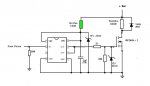
I have breadboarded a 28X2 driving, via PWM, a MCP1407-E/AT (MOSFET driver, 6A) in turn driving an IRL640BPF (n-channel power MOSFET, 200V 17A). The 28X2 is connected directly to the driver (with a 10K pulldown). The driver is connected to the power MOSFET through a 20 Ohm resistor (also with a 10K pulldown). The power MOSFET source goes to the common ground and drain goes to the load (a small 12V lightbulb) in turn connected to separate +12V power. VDD to the driver is same 5V source as to the 28X2, through a 50 Ohm resistor (and a 1uf cap to ground). All this is per a circuit diagram posted to another thread a while ago. I also have a blinking LED on the 28X2 to see if the thing is running.

The problem is that the circuit will not activate on program download or, after a reset which lasts longer than about 2 seconds. There are however two repeatable ways to get it going:

One is to remove VDD from the driver. The circuit then operates normally (LED blinks, the proper (& clean)PWM input arrives at the power MOSFET input (as per oscilloscope reading) and the load light bulb brightness is proportional to the PWM duty factor. If driver VDD is then reconnected, the circuit continues to operate exactly as before (but with slightly higher PWM voltage at the power MOSFET - about 4V).

The other way is to move the driver input from the 28X2 PWM o/p to the LED o/p. The load bulb will then flash in unison with the LED (as expected). If the driver input is then quickly switched back to the PWM o/p, the circuit begins to operate normally.

When the driver input is removed from the PWM o/p, the LED immediately starts blinking. The same happens when the load bulb is disconnected from the power MOSFET. If the PWM o/p or load bulb are reconnected however the LED stops (and there remains no PWM output signal).

I have also found that a reset (during normal circuit operation) of less than about 2 seconds works normally i.e. the circuit stops functioning on reset and resumes on reset off. One odd thing however is that when the circuit is not operating (no LED or PWM o/p, the chip will still accept a program download so it looks like it is not completly halted).

Similar behaviour BTW is noted when the driver is removed entirely from the circuit (28X2 PWM o/p connected directly to the power MOSFET). If the power MOSFET is disconnected, all works normally up to the driver output.

The reset and serial pins I/O are terminated properly.

It appears that the power MOSFET is interferring somehow with the 28X2 but I have no idea how or why. If anyone has any insight I would be much appreciative as I'm out of anything else to try.
 

Dippy

Moderator
Absolutely.
Nosmoke; help us to help you and post a nice clear diagram and a couple of sentences describing the application.
Loads of text to describe your problem is good but a diagram will put it into context and usually saves at least 150 words.;)
 

Goeytex

Senior Member
I think this is the schematic since it is the only one that uses a 50 ohm current limit to the
MOSFET driver.

The 50 ohm resistor is optional as well as the 10K pull down at the Picaxe Pin, the 10K to the
MOSFET gate, and the 2 Zeners. These were included because the OP on the other thread
was having severe noise issues that was toasting the MOSFET driver. (The 50 ohm resistor
in this circuit was based upon a supply voltage of 13.5v) and may limit current too much
with a 5v Supply (100ma max)

A 1K series resistor from the Picaxe (not shown) to the driver input is generally a good idea
for protecting the Picaxe in case of a unexpected catastrophe.

What we need now is the rest of NoSmokes schematic showing the Picaxe and all other
connections, as well as the 5v power supply details .
 

Attachments

Last edited:

MPep

Senior Member
VDD to the driver is same 5V source as to the 28X2, through a 50 Ohm resistor (and a 1uf cap to ground)
In the diagram posted by GoeyTex, the Zener is 15V, NOT 5V!!!!!!!!!!!!!!!!!!

Houston.....we have a problem!
The PICAXE is, of course, not designed for 15V operation.
 

Dippy

Moderator
"The power MOSFET source goes to the common ground and drain goes to the load (a small 12V lightbulb) in turn connected to separate +12V power. VDD to the driver is same 5V source as to the 28X2, through a 50 Ohm resistor (and a 1uf cap to ground)."

This doesn't appear to agree with diagram."VDD to the driver is same 5V source as to the 28X2,"
Vdd to the driver comes from +Bat (12V?) in the diagram.
What's the 50Ohm res for? You don't want any impedance in that path.
In any event , the Vdd to the driver should be completely separated from , in this case, the PICAXE +supply.
Sounds confused.


Perhaps we need a full and up to date diagram.
 

Janne

Senior Member
Well the driver circuit looks decent. 50 ohm resistor on the supply is defeating the purpose a bit, it would be better to have all the series resistances in series with the FET gate. If it's for filtering power supply spikes, you need to also have a bigger electrolytic capacitor besides the 1µF decoupling cap.

As the driver looks ok, I'd suspect the picaxe circuit itself. How have you wired that part up? The problem could also be breadboard-related, switching circuits and breadboards don't go together too well.

edit. If the picaxe indeed is sharing the VDD with the FET driver, then there is a big problem. Picaxe will need it's own 5V supply.
 
Last edited:

Goeytex

Senior Member
In that diagram the Picaxe supply was separate from the 12v supply to the Driver.

If this circuit is used with a 5v supply to the driver that is shared with the Picaxe supply,
the 15v Zener will not do much of anything except shunt spikes greater than about 15v.
 

MPep

Senior Member
In that case, the driver won't do much either. You'll only be able to drive the Gates with upto 5V, setting the MOSFET up in its linear region (think HEAT).
 

Goeytex

Senior Member
Sure. depending upon the Mosfet's Gate Threshold Voltage, powering a MOSFET driver with 5v may not make much sense.

However, in this case, the OP is using a Logic Level IRL640BPF which has a Gate Threshold Voltage of about 1.5V , so the driver is doing it's job of providing 5v with more than adequate current.

The MOSFET will not be in its linear region any longer than if there were 12v provided to the Driver. The heat generated will not be because of inadequate Driving , ( 5v is more than adequate for this FET), but rather because of this MOSFET's relatively high RDson of about 180 milliohms.
 

Dippy

Moderator
Has anyone clarified the "VDD to the driver is same 5V source as to the 28X2, through a 50 Ohm resistor (and a 1uf cap to ground)." or are we in crystal ball land at the moment?

Is the driver at 5V? How? I'd assumed +Bat = 12V.
The circuit posted shows +BAT via 50Ohm to driver with a 15V zener. Is the +Bat 12V?
Surely the 15V zener isn't meant to be 5V and the PICAXE power gets tapped off there?
If so, that's less than ideal.

The OP says a PWM max at gate of 4V. That's not very good - assuming Vdd=5V and measurement accuracy OK.
As to heat; do we know the spec of the "small" 12V bulb?

Are we discussing something which isn't clear?
 

Goeytex

Senior Member
Has anyone clarified the "VDD to the driver is same 5V source as to the 28X2, through a 50 Ohm resistor (and a 1uf cap to ground)." or are we in crystal ball land at the moment?
Crystal ball land I imagine. The 50 ohm resistor should be removed as well as the 15v Zener. I assume that the 1uf cap is as in the diagram.
The diagram was specifically for a problematic circuit and not intended for general use.

The OP seems to have adopted this specialized driver circuit (intended for something else) for use with a common 5V supply for both the Picaxe and Driver. I don't think the OP is using 12v at "+ bat" and then tapping off the 15v Zener as this indeed would be problematic.

The 4 V at the gate is likely related to retaining the 50 resistor, if we assume a precise 5v supply. However the IRL620
should go into saturation at about 3.7 volts. But as you said, 4V is less than ideal. This FET likes 5 - 8 volts at the gate
with 10 volts being the "Absolute Maximum".

Until noSmoke posts a complete and accurate schematic we are relegated to gazing into the crystal ball.
 

Dippy

Moderator
Yes, I think I'll go and gaze into my coffee and work out how to drive a 350,000 rpm AC motor as I'm scratching my bonce a bit.:(
 

NoSmoke

Member
Thanks folks for the quick replies. I will try to clarify the ambiguities:

First, the schematic referrenced by Goeytex is different than my circuit in that the driver is powered by the same 5V going to the Picaxe. I made that change as the MOSFET is a "logic-level gate" device (with a max of 10V gate input). I have a separate 12V power supply going to the MOSFET for experimental purposes but ultimately will have about 120V (DC) on it when the device is connected to my wind mill. The 5V and 12V supplies are connected to the common ground.

I included the 50 Ohm, 1W resistor as it was on the schematic but did wonder about its purpose (same for the 1uf cap).

The circuit seems to work in a similar fashion w/o the driver in that the PWM level to the MOSFET gate is only slightly lower than with the driver (a little less than 4V) but I assumed the driver was required to supply adequate drive current to the MOSFET gate. In any case, the MOSFET data sheet says it can be driven satisfactorily by 4V. When the circuit is functioning now, the MOSFET does not heat up (but I guess that might change at higher amps).

The load is simply a 12V turn signal bulb so I assume it draws acouple of amps or so.

I don't have yet a good means of posting a schematic but in summary the circuit is the same as that posted by Goeytex with the exception of powering the driver from the Picaxe 5V supply instead of the 12(?) volt battery and, the power MOSFET is an IRL640PBF. The driver is a MCP1407 but is the through-hole type with a different pinout than that shown on the schematic if that makes any difference.

I hope that helps. I too am wondering about breadboarding a switching circuit with the noise implications et al. Another thing I should have mentioned is the circuit works properly if the PWM duty cycle is set to 0 or 100 so it looks like switching noise may well be the culprit.

Thanks again for everyone's input..........
 
Last edited:

Dippy

Moderator
Can we assume that you are fairly new to electronics?

"I included the 50 Ohm, 1W resistor as it was on the schematic but did wonder about its purpose ..."
- remove the 50Ohm. It degrades the performance. Where did that come from? This could be a problem when cutting'n'pasting designs.

"(same for the 1uf cap)."
-I suggest you READ the driver Data Sheet which explains the purpose and gives you tips.

"...but I assumed the driver was required to supply adequate drive current to the MOSFET gate."
- PEAK drive current. Basically, you are charging/discharging a capacitor when driving a MOSFET gate.
So, if you are doing fast PWM then you need the driver as coulombs are whizzing in and out, if you are pulsing at 1 plop per second you could drive it with a piece of putty :)

"(but I guess that might change at higher amps)."
- obviously , the MOSFET has resistance. No guessing required.

"The driver is a MCP1407 but is the through-hole type with a different pinout than that shown on the schematic if that makes any difference"
- the pinout doesn't matter as long as you have done it correctly. The posted schematic is correct for DIP8 (through hole), what are you using?


If you don't have CAD then draw it neatly with a ruler , then photo/scan it, jpg it, and use 'Manage Attatchments' button to post it. Try and get it in focuse, some of the images posted are so blurry that they may have well posted a photo of the dog.;)

Good luck with the project.
 

Goeytex

Senior Member
NoSmoke,

I don't see where you can be assisted any further unless you decide to post a complete and accurate schematic of the
actual circuit you have breadboarded. That means including every single component on the breadboard, leaving NOTHING out.

It may very well be noise, but then again it may very well not be. It could be a lot of other things too.

In my opinion, attempting a project where there is high speed switching and high power FET's without having an oscilloscope and
a good DVM is asking for a lot of tail chasing and frustration.

Good luck.
 

NoSmoke

Member
Dippy:

Yes, I am fairly new to electronics. I trust that is not an issue on this forum.

The 50 Ohm was on the schematic provided by Goeytex (or whomever was the originator). I did try removing it and it made no difference I could see.

The MCP1407 comes in three package types (I did READ the data sheet but missed the bit about the decoupling capacitor(s)) DIP, DFN (surface mount?) and, TO-220 which is what I have. In any case, as I mentioned, removing the driver from the circuit does not cure the non-startup problem. I have also read the MOSFET data sheet but could not find anything there which might shed light on the problem.

I'll see if I can draw a decent schematic and photo it.

I'm still curious though why when the picaxe appears to be "stalled" (no PWM o/p or flashing LED) the programmer can still download to it.

Goeytex:

Any suggestion as to what the other things could be (other than noise)?

I do have an oscilloscope (and DVM) - that's how I viewed the PWM waveform and measured its amplitude.
 

NoSmoke

Member
Thanks eclectic - I'll try it out.

Have also shortened a couple of the breadboard jumpers and the circuit now starts reliably! I guess maybe breadboards and switching circuits don't really mix or at least not very well. Now on to feeding the mosfet 120VDC (and higher amps) and see what happens.

BTW, is Middle England anywhere Middle Earth?
 

Goeytex

Senior Member
Have also shortened a couple of the breadboard jumpers and the circuit now starts reliably!
Have you perhaps not used a bypass capacitor on the Picaxe V+ Pin ? What about a bulk/filter capacitor
where power comes to the breadboard ? Do you have one ?

Now on to feeding the mosfet 120VDC (and higher amps) and see what happens.
What will happen is that your FET is gonna get hot. Your FET has an ON Resistance of 180 miliohms
so at high current and high voltage it must dissipate quite a bit of heat. I hope you have it on a nice
big heat sink.
 

Dippy

Moderator
"Yes, I am fairly new to electronics. I trust that is not an issue on this forum."
- no, but it helps others adjust their response and assumptions.:)

I'm glad you have it sorted. I hope you can see how a description of the physical layout and an up-to-date schematic could have helped here.

Breadboards are great and, for my sins, I have abused mine quite a lot with current and voltage.
However, I wouldn't push your luck too far as the contact area is going to be a lot less than solder joints.


"Now on to feeding the mosfet 120VDC (and higher amps) and see what happens."
- it'll get hot and maybe blow up and you might get a shock.

The better your drive quality the cooler it'll run, but please take note of Goey's comments re heatsinking.
Have you done any calcs on DC heat generation in the MOSFET? Even a simple IsqR?
It doesn't take many watts on a bare TO220 to melt it.
 

NoSmoke

Member
Goeytex:

I don't have a Picaxe bypass cap although I tried one and it didn't seem to help (I like the minimalist approach but maybe in that case it's not good practice). The 5V power supply I have has substantial filtering (can't recall offhand the filter caps size) and the o/p is flat as a board with no noise I can discern on my scope.

As far as hot MOSFETs, I certainly plan on suitable heatsinking at the higher amp range which in my case should peak out at around 9 or 10A.

Dippy:

Not to be too argumentative but I'm not sure how a physical layout or specific schematic would have helped in this specific instance unless the physical layout was so detailed I guess to include connecting wire lengths/routing (as shortening a couple of the wires was apparently sufficient to cure the problem, at least so far; maybe at higher MOSFET loads the problem will reappear).

When I feed the MOSFET at higher currents, I will not be using the breadboard for the MOSFET contacts. I have already constructed the power portion of the circuit which contains a heatsinked 3ph rectifier (for the wind mill o/p), the heatsinked MOSFET, load connectors and the two resistors + zener immediately upstream of the MOSFET gate.

I haven't done any heat calcs - just assuming the 17A rating of the MOSFET and adequate heatsinking will suffice. For heatsinking, I have short pieces of 1 1/2" angle iron - if not enough, will try something more substantial.

One other thing I'm wondering about is RF noise generation, especially when the circuit is connected to the long wind mill power line. Haven't noticed any so far though using an AM radio.
 

John West

Senior Member
Dippy:

Yes, I am fairly new to electronics. I trust that is not an issue on this forum.
<snip>
It most certainly is an issue. We answer newbies questions far differently than we do experienced user's. Answers to newbies need to be much more detailed and complete, and we make far fewer assumptions about their knowledge base in electronics and programming. Time-wise, it's often the difference between a one line answer answer and a very long post, so it helps greatly to know a good bit of detail about the experience level of the person posing a question to the forum.
 

John West

Senior Member
With bypass capacitors as small and inexpensive as they are, it seems to me that not using one is a "minimalist" approach in the same way that not tying one's shoes is a minimalist approach, or not putting the gas cap back on one's car is a minimalist approach. Minimalist it is, wise it is not.
 

srnet

Senior Member
One other thing I'm wondering about is RF noise generation, especially when the circuit is connected to the long wind mill power line. Haven't noticed any so far though using an AM radio.
Try a AM radio on Long Wave ..........
 

NoSmoke

Member
With bypass capacitors as small and inexpensive as they are, it seems to me that not using one is a "minimalist" approach in the same way that not tying one's shoes is a minimalist approach, or not putting the gas cap back on one's car is a minimalist approach. Minimalist it is, wise it is not.
That's not really the point. A "minimalist" approach IMO is part of the fun of experimentation - seeing what may be necessary and what may be not, according to one's own experience. That's why I am doing this - it's a hobby. Perhaps I will add such stuff in the end but in the meantime I'll continue to try things, within reason, to see what or what does not happen. What else can I say - I like to question assumptions. YMMV.
 

John West

Senior Member
Good point, sernet. On Longwave, I can hear the harmonics of the sweep frequencies of nearby TV sets. Not so nearby ones, as well. And the fundamentals REALLY radiate. Just because someone thinks the upper harmonics aren't significant doesn't mean that the lower harmonics aren't wrecking havoc on other frequencies right down to the fundamental. Good filtering is more than a good idea technically, it's a show of consideration for your neighbors.
 

Dippy

Moderator
"Not to be too argumentative but I'm not sure how a physical layout or specific schematic would have helped..."
I don't want to be argumentative either , I agree , no need ... let's look back.

Post#1 A long description. Clear-ish , well spaced, but no link to circuit or attached circuit, which would have saved a lot of typing.
The whole point is to remove confusion and ambiguities at stage 1.

Post#4; Goey kindly spends time looking for and posting what is apparently your circuit.

Posts #5 to #14. Attempts at suggestions based on (and no-one's fault) assumed circuit.

Post#15 (!!). You say "First, the schematic referrenced by Goeytex is different than my circuit..."
Oh no.... here we go.:eek:

Therefore, if you'd posted a schematic it would have:-
A) Clarified immediately the driver and PICAXE connections.
B) Allowed us to check the PICAXE end of your circuit to see if there were any oddities there.
We see loads of little mistakes here on the Forum in general, so how, without a latest and accurate schematic, can we eliminate slight errors in your circuit?

Maybe that helps a bit?


Please remember (and I'm on my knees begging) people are spending their time to help you and therefore are hugely grateful for clarity. So just have pity on us poor old devils who creak out of our armchairs to help.
:eek:

Anyway, point made I hope constructively, time to move on.
 

John West

Senior Member
Most of the folks who have questions for the forum are attempting to make their circuits work reliably. If you aren't, then have fun, and wear safety glasses. Even low voltages can do dangerous things when handled improperly.
 

MPep

Senior Member
That's not really the point. A "minimalist" approach IMO is part of the fun of experimentation - seeing what may be necessary and what may be not, according to one's own experience. That's why I am doing this - it's a hobby. Perhaps I will add such stuff in the end but in the meantime I'll continue to try things, within reason, to see what or what does not happen. What else can I say - I like to question assumptions. YMMV.
Whilst the minimalist approach can indeed be good, IMO, it often comes ONLY after extensive testing with a proper setup. Once a circuit is working correctly, with all the 'bells and whistles' as it were, then start taking out parts. You know how the circuit works (worked!!), what is the outcome now?
In the early days of CRT TVs, price conscious manufacturers would design a circuit board, then start removing bits (coupling and decoupling caps, resistors etc) until the TV no longer worked. Put back the last removed part, and viola, there goes a new model TV that works. Those removed bits might cost, all up, about $1, but in the course of a production run of 100,000 it adds up, and would lower the profit margin!!

For one-off circuits, I generally make them robust enough to accommodate all forseen problems, ripple etc, so the circuit becomes 'bulletproof'.

Take a look here. Jeroen has taken the trouble of minimilising a circuit, but only after quite a bit of study of datasheets. Not down lightly, but the results can be very successful.

Regarding a circuit diagram, even MS Paint can help here if you have no other means.

MPep.
 
Last edited:

MPep

Senior Member
Most of the folks who have questions for the forum are attempting to make their circuits work reliably. If you aren't, then have fun, and wear safety glasses. Even low voltages can do dangerous things when handled improperly.
In case of exploding MOSFETs, have several spare underpants handy too.
I speak from experience when I say this, coz when they go, they REALLY go.
My experience was with 12/24V inverters (to 230Vac in NZ). The caps stored a lot of energy, until the MOSFETs blew.
 

Goeytex

Senior Member
Assuming adequate drive voltage & current FET heat dissipation can ballparked using Power = I^2 * R. For example
10 amps X 10 Amps X .180 ohms = 18 Watts. Then multiply that by duty cycle. (This does not account for
switching losses.)

A "minimalist approach" might better suit someone experienced in electronics that understands what can possibly be
minimalized and what cannot. In the case of a high current switching circuit probably on of the last things to omit
would be bypass capacitors. Even then a smarter "minimalist" approach would be to include the time and excperience
proven things in the beginning and then try removing stuff after it's working properly already.

Seeing a flat line on a scope to gauge power supply noise, suggests that you used the DC setting on the scope. Change it
to AC and move the trace to center screen. Then change the voltage range to 10 mv per division. It won't be flat anymore
unless the supply is a battery. .
 
Last edited:

MPep

Senior Member
Assuming adequate drive voltage & current FET heat dissipation can ballparked using Power = I^2 * R. For example
10 amps X 10 Amps X .180 ohms = 18 Watts. Then multiply that by duty cycle. (This does not account for
switching losses.)

A "minimalist approach" might better suit someone experienced in electronics that understands what can possibly be
minimalized and what cannot. In the case of a high current switching circuit probably on of the last things to omit
would be bypass capacitors.
My point exactly!

Seeing a flat line on a scope to gauge power supply noise, suggests that you used the DC setting on the scope. Change it
to AC and move the trace to center screen. Then change to voltage range to 10 mv per division. It won't be flat anymore
unless the supply is a battery. .
In a previous company I worked for, we were given to use a Fluke 178 multimeter. This has the advantage of being able to show AC and DC in the display at the same time. This came in VERY handy as sometimes the DC would look ok, but the circuit still didn't work correctly. Dual display the measurement, and lo and behold, you'd find 10Vac on a 130Vdc supply rail. Definitely NOT good. Renewing the appropriate reservoir capacitor would solve the issue! This was in gyrocompasses. :)

I wouldn't necessarily say that about battery supplies. If a lead acid battery has sulphated, or does not have enough electrolyte, it acts as though it has series resistance, and then any pulsing caused by the circuit in question, would show up as ripple on the suppply rails.
 
Last edited:

Goeytex

Senior Member
I wouldn't necessarily say that about battery supplies. If a lead acid battery has sulphated, or does not have enough electrolyte, it acts as though it has series resistance, and then any pulsing caused by the circuit in question, would show up as ripple on the suppply rails.
Anyone who has messed around with desulfator circuits and lead acid batteries knows the large pulses that can be generated as the battery acts as a resistor, a capacitor and an inductor. Sucking large currents out of a battery, with a fast turnoff can induce spikes, ringing. etc. This is where inductive filters, bulk capacitors, clamping circuits, etc can be very useful.

However, what I said above was that if the signal was flat on AC 10mv then the source was ( extremely likely) a battery, which does not necessarily imply that if the source is noisy that it is not a battery.
 
Last edited:

John West

Senior Member
All batteries have internal resistance inversely proportional to the amount of current they can deliver. It's that very resistance that's the reason the Rev.Ed. folks recommend using small batteries on new projects until they have been verified as properly functional. You can get the same result by using a resistor in line with a well regulated high current power supply if it lacks conveniently adjustable current regulation.

With projects that by their nature are high power, that trick won't work, and a large battery or a high current power supply is a necessity. A well regulated power supply with adjustable current control can save your project, and save you a possible injury. To protect myself and my circuitry during initial testing I've even been known to use a current limiter circuit on the output of a large battery.
 

NoSmoke

Member
A "minimalist approach" might better suit someone experienced in electronics that understands what can possibly be
minimalized and what cannot. In the case of a high current switching circuit probably on of the last things to omit
would be bypass capacitors.
I regard to bypass caps, I have found the following article on the design of gate drive circuits which it appears can get quite complex with many variations. I haven't been able to figure out though which one of the types discussed is the MCP1407.

http://www.google.ca/url?sa=t&rct=j&q=mosfet bypass capacitor&source=web&cd=2&ved=0CCQQFjAB&url=http://www.ti.com/lit/ml/slup169/slup169.pdf&ei=iK61Tu7QOe3QiAKj6tRA&usg=AFQjCNHD0uDRBD6OjJ7EZho_-DGLeTYaBA

It delves into the necessity of bypass capacitors for direct drive apps (the PWM controller driving the MOSFET directly) but since the MCP1407 driver also requires a bypass, a "minimalist" approach would not I guess exclude it.

You do however refer to bypass capacitors (in the plural). Does this refer only to the 1uf cap on the schematic (from driver VDD to ground) or to others as well that might be required but aren't shown on that particular schematic (perhaps for higher voltage & curent apps)?

Thanks again to all for your help.

BTW, have now connected the MOSFET to the mains via a bridge rectifier and am controlling current to a 100W light bulb. No sparks, flames or heat and the circuit starts reliably!
 
Last edited:

NoSmoke

Member
MPep:

Thank you for the minimalizing reference. Re an LED's light sensing capability used to reduce part count, the site also references a v interesting topic you might worthwhile:

"Very Low-Cost Sensing and Communication Using Bidirectional LEDs"

Sounds like a fun thing to experiment with........
 
Top