problem after another! :)

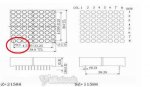
This is a very simple question and normally I try to give a really detailed question. This might be a little brief but hopefully every one understands. You might know that I am in the process of just having a little picture on an LED matrix. I received them this morning and it worked! But this time the problem made me laugh :L. When I was flicking through the 24 pins (that's odd shouldn't there be only 16?) I realised I was getting green and red. In a sense this is good because it forces me to use both of the colour which I am more than happy to do! OK now I have a really good diagram and a little information about bi-colour led matrix's but one slight problem! Which pin is 1 and which is 13 ? The document says there should be an indicator but there isn't! :L Hopefully some one can help thank you :)

Here is a quick video of the Matrix itself :):http://www.youtube.com/watch?v=8cSt8PieOgw&feature=youtu.be

And if any one can see any think i can't or have bought a similar item: http://www.ebay.co.uk/itm/320726819510?ssPageName=STRK:MEWNX:IT&_trksid=p3984.m1439.l2649

Thank you all so very much and have a wonderful Christmas! (hopefully i can be kitted out with more electronic components! :))
 

fernando_g

Senior Member
The image on the website shows the legend: HGD308BAC. Googling it returned no results...:(

Are there any other markings? You could google them.
If still no results are found, you have two options; 1) ask the seller for info (good luck on that), or 2) painfully and slowly determine by trial and error how the matrix is connected.

You are correct, that in a classic row and column addressable matrix there should be 16 pins only. But you never know if some of those pins are no connects or if a non-standard arrangment was used.

Many moons ago, I purchased a 10 segment surplus bargraph for a VU meter I was building....same scenario as yours (although far simpler). It had 13 pins. It turned out that not all of the LEDs were R+G, some of them were R only and were arranged in a separate bank which had a separate anode connection! And the R+G bank had two anode connection (one for each color).

So one common anode plus 4 individual cathodes for the R bank, and two common anodes plus 6 individual cathodes for the R+G bank. 13 pins.
Sounds easy now, back then it took me some sweat to figure it out.

These are the type of challenges found when one purchases surplus components, one is truly navigating in uncharted territory.
 

Goeytex

Senior Member
If there is no markings ...... then Pin 1 is on one corner and Pin 13 will be on the opposite diagonal corner.

Using a 5 volt supply and a 1K current limit resistor you can apply power to diagonal corner pins and see which
led lights up. If nothing light up then reverse the polarity. Then looking at the row column diagram you can deduce which pin is Pin 1 and which is Pin 13 by which led lights up .
 
Thank you very much for all your replies, earlier today i was attempting to figure it out. yes it is rather muchly a boring obstacle but yes you are right that is the problem about buying cheap components :L I have already messaged the seller and hopefully he can tell me (cross fingers). At the moment i am just going to figure out the reds and then just build a circuit then advance and hopefully fix it to my head! I will have to make my own data sheet! :L Thank you all again :)

If I use this a lot ':L' It just means a laughing face (Don't ask me why I already have tried figuring that out, last time i checked my face didn't look like that when i laughed ;) ) Thanks again Trevor Boultwood :p The other marking on this chip is JX-1588BHG ( when i searched 1588BHG i got a couple of results no better than the other ones I found though)
 

jtcurneal

Senior Member
Looking at the web page, it appears that there are 12 pins inline on each side of the LED matrix and that the pin 1 is the third pin from the end.

If your LED matrix has 24 pins, maybe the 2 pins and the last 2 pins on each line are not connected.

Uou may have to use the technique that Goeytex suggested to check which pins are connected to which LED.

Joel
 

SAborn

Senior Member
One option would be to have a look at the data sheet on Sureelectronics web site as they sell the same sort of thing, and it might make the testing a little easier.

I guess you did see the text on the schematic pointing to pin 1 didnt you?
8X8.JPG
 
Ohh my comment didn't save :/... I'll re write it!

Ok after spending an hour doing every single combination I worked out the pin outs myself. And thanks StigOfTheDump but I am afraid I tired that datasheet earlier and it just confused me, because There are two sides which possibly could be the side with pin 1! :L
Any way I worked out that the two sides contain 4 anodes and 8 cathodes making it a common anode matrix. This made it a lot easier to find out which pins I will need and it most likely took a lot faster.

Ok so i have just hit another problem, I not only have to worry about the frequency of the multiplexing but I also have to worry about the frequency of all of the pins to make the pins look orange. Because it seems you can't just turn on both cathodes because it just displays it as red. Maybe because the red has a lower resistance? Not to sure. (if i connect the same segment to red and green green is not shown making it not look orange).

P.S As I don't have all the transistors yet I will just use it without making just simple patterns at the moment so i don't source to much current to blow the pic chip. and does any one have any cool symbols or logos I could display on the matrix.

Thank you all so very much :) I will keep this updated! :)
 

Hydroid

Senior Member
Ok so i have just hit another problem, I not only have to worry about the frequency of the multiplexing but I also have to worry about the frequency of all of the pins to make the pins look orange. Because it seems you can't just turn on both cathodes because it just displays it as red. Maybe because the red has a lower resistance? Not to sure. (if i connect the same segment to red and green green is not shown making it not look orange).
I used what appears to be a similar, if not the same, display which I bought from Sure Electronics (via eBay). I used it in a clock display where I wanted three colours: Red, Green and Orange. I made myself a test board with one of the display units (I bought a set of 10) so I could experiment. I found that using a 220 ohm resistor on the common cathodes for the red rows, and a 150 ohm resistor for the green rows, gave the three colours I was after with 5V applied. Here's a photo - quality's not the best (late night shot with an iPad) but it shows the three colours.

photo.JPG

My actual clock board uses transistors on the column and rows, for multiplexing, but the effect is the same, so you should be able to get orange. Are you using current limiting resistors to adjust the red / green current in order to balance the intensity ?

Regards, John.
 

BeanieBots

Moderator
As Hydoid suggests, if you use current limiting resitors (or current drive) you can easily get orange.
The reason you only get red when you connect both pins to a single current limit resistor is because the volt-drop of a red LED is much lower than that for a green LED and so it takes ALL the available current.
Try using a resistor for EACH pin and see what happens.
 

SAborn

Senior Member
Little OT but good to see BB is back, its almost been a annual event to see a comment, i was starting to think he was lost in the pub, then maybe he was and has been kicked out for Xmas closing.;)

Merry Xmas BB.
 
Thanks to both of you, Orginally i didnt' have any resistors connected to the cathodes so that must of been the problem. I now have another :D! This should be the last one...

No it shoudln't while writting this I just remembered that I need a current limiting resistor on the base of the transistor to drive the cathodes of the LED's . Thanks to all! I shall keep updating this as my project increases.

I was thinking this morning if i wanted to control ever led (128) then I would need 24 pins!? So For now I shall just drive one colour :/.
I will make a little pattern that shall just be like a snake or some think like that. Then I shall use some multiplexing to just flash 'T''R''E''V''O''R' :)
Then I shall make a strip board circuit to solder all 24 transistors and pins to connect them to a breadboard.

I will then hopefully start researching about the MAX7219 Which may require me to go to a sub project to learn about the ic2 :) Then hopefully start making some stuff like scrolling messages! Cross fingers it all works out! :p
At the moment I am just waiting to receive all those transistors! :p! Good day every one and have a lovely Christmas!
Trevor Boultwood
 

BeanieBots

Moderator
Thanks SAborn, Didn't think I'd been away all that long but things have really changed here. (except Dippy of course).
New forum, new moderators, new members. Even a few new problems!
 
Hahaa! that made me laugh! I have seen some very interesting videos with LED,s. So I am guessing you can control a PWM with the 7219? That is really cool! Do you think it is possible to any one to give me a small example code? Like how to initialise? I don't mind donating because I really want to learn how to use the I2C command and I think the best way of teaching yourself a command is to look and study a example and modify it, until you become familiar of how it works.

Thank all so very much, I might take up your offer and buy myself one of those RGB matrix's as the Love heart looked really cool. (I don't know If it would make a girl fall in love with me though :L) But Thank you :)

Trevor Boultwood
 

Dippy

Moderator
"I don't know If it would make a girl fall in love with me though"
- no it wouldn't Trevor, it's uncool, she'd probably throw up :)

I'm glad to see BB back too.
Me a treasure?
I've been called a lot of things (especially on this Forum), but "treasure"...? Lordy! ;)
 

SAborn

Senior Member
I've been called a lot of things (especially on this Forum), but "treasure"...? Lordy!
Its only a figure of speech, so dont let it go to your head.

More so a expression of gratitude to the help and dedication both of you give freely to others, and to let you know from my point it is very much appreciated.

As a moderator on other forums i do understand the behind the scene crap you need to deal with, lead alone respond to threads, so it is my humble way of acknowledging you for your services rendered.

Merry Xmas to you all.

Pete.
 

BeanieBots

Moderator
I'm sure Dippy won't mind me helping out with the occaisional "how to drive a FET" thread!

Trevor,
Stop reading up on I2C, the MAX7219 uses SPI.
It's simple enough.
Step 1. Download the MAX7219 datasheet and read about what the registers do.
Connect up your X2 PICAXE to the dedicated SPI pins. (PICAXE SPIout to 7219 Din).
Connect the PICAXE SPI clk to 7219 clk pin.
Pick another PICAXE output pin and connect it to the 7219 CS pin.

Enable SPI (HSPIsetup spimode11e,spifast)
Then send data to registers. (HSPIOUT register,data)

Yes, you can vary the LED brightness using the appropriate register.

Martin has posted a lot of very good info about driving the 7219 but the hardware SPI commands now make it a lot easier.
 

Dippy

Moderator
I watched your vid. Well you're nearly there Trevor. An up to date schematic may help others to solve your dim bits.

Will you be getting a camera tripod for Christmas? I'm feeling sea-sick ;)
 
hahaa! I will attempt to pick one up from Tesco when I next go ;) hahaa! I am ever so sorry for the quality of the video. Any way I am also sorry for getting the wrong code ! (I2C;) It's SPI!!) Soo I saw a really good deal on eBay to pick up 10 of those max7219 for only 3 pounds! SO I have ordered one of them to use. They won't come for another 15 days so in the mean time I will continue just to make my own codes to show letters :D (Very difficult, I did the T and thought that was hard! That is just two lines really :L). OK, By the sounds of it, it isnt as hard as I first thought. it looks like just selecting registers and sending them over?

Any way, I won't need the 30 transistors I just ordered -_- But I suppose I can use them for a lot of things in the future without out the need to go out to Maplin every time I need one :L. And My last question for the max7219 for the moment is, I always see people do things like:
Eprom 'hex decimal' and stuff like that.
Will I need to do this? Or is that just a reference or a label to save memory?

Thank you all and hope you had a very nice Christmas.
 
Thank you Armp I had a good one! Hope you did to :p. I kind of expected for the cips I bought to be a little.. 'crap'? If that is the right word? Hahaa! Well If any one sees this link and have bought them, please feel free to tell me how these chips were with your projects :L I suppose they were only a couple of quid :S But I hope they are good as I will have to wait just over half a month to receive them! That reminds me, I shall do my annual Christmas shop at the picaxe shop to stock up on PIC's ;) :) Thanks again for the feedback Martin, I heard that you have done a lot of work with these chips and I was suggested to look at your work :) See you in the future.
Trevor Boultwood
 
OK, Now I was a little optimistic, I was looking through your replies etc, and I didn't really understand any of the stuff. I was even trying to find a schematic on how to connect everythink up. :/ I was mainly thinking this one:http://1.bp.blogspot.com/-eoQHWW-2C1k/TiwMr-wZpMI/AAAAAAAAAZc/TOqyK7MedYc/s1600/max7219_07.png

This one has the two connections 'clk' and 'din' but there were some others with resistors witch are a little confusing :S Should i connect it up just like that (Of coure replace the PIC with a picaxe). Then I have no understanding about the initalisation nor how to hous to send the registers over :/
 
I am just about to buy a PIC chip. I remember seeing a comment about buying the 28x1? I don't mind but could I just not use the 20X2? Because it is smaller and a little cheaper. Also is there not a 20X2 as well? Thank you all again! :)

Trevor Boultwood
 
Top