I am trying to construct a latching power switch with the following specifications:
1. 3.3V/5v, 200ma operation
2. push button on-off
3. power on-off from a microcontroller
The Pololu Lv switch satisfies requirements 1 and the off requirement of 3,
http://www.pololu.com/catalog/product/751
A basic latching switch was discussed widely in this link,
http://www.eevblog.com/2012/03/30/eevblog-262-worlds-simplest-soft-latching-power-switch-circuit/
The above switch was improved upon with mosfets here,
http://img36.imageshack.us/img36/420/davidlw.png
Post #10 of this thread by KMoffett has a design similar to the Pololu switch, 08MSWT.jpg,
http://www.picaxeforum.co.uk/showthread.php?7718-Regarding-emergency-stop
And here is another latching switch,
http://www.discovercircuits.com/DJ-Circuits/latch-cir6.htm
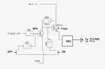
My problem is that I cannot find a design that will turn the switch ON under software control. My thought was to use an analog SPDT such as the
TI SN74LVC1G3157 in parallel with the push button. Unfortunatly, I ordered parts from Futurlec and they have my order on hold waiting for supplier SMD adapters. I have the analog switch, but before I order the mosfets from a reputable supplier I thought I would ask about the basic feasibility of trying to integrate the analog switch.
Baxter
1. 3.3V/5v, 200ma operation
2. push button on-off
3. power on-off from a microcontroller
The Pololu Lv switch satisfies requirements 1 and the off requirement of 3,
http://www.pololu.com/catalog/product/751
A basic latching switch was discussed widely in this link,
http://www.eevblog.com/2012/03/30/eevblog-262-worlds-simplest-soft-latching-power-switch-circuit/
The above switch was improved upon with mosfets here,
http://img36.imageshack.us/img36/420/davidlw.png
Post #10 of this thread by KMoffett has a design similar to the Pololu switch, 08MSWT.jpg,
http://www.picaxeforum.co.uk/showthread.php?7718-Regarding-emergency-stop
And here is another latching switch,
http://www.discovercircuits.com/DJ-Circuits/latch-cir6.htm
My problem is that I cannot find a design that will turn the switch ON under software control. My thought was to use an analog SPDT such as the
TI SN74LVC1G3157 in parallel with the push button. Unfortunatly, I ordered parts from Futurlec and they have my order on hold waiting for supplier SMD adapters. I have the analog switch, but before I order the mosfets from a reputable supplier I thought I would ask about the basic feasibility of trying to integrate the analog switch.
Baxter
")