Power Supply Prob , not strictly Picaxe

donrecardo

Senior Member
Hi , I know its not stictly a Picaxe question but can someone help me out.

I am making a power supply to give ...

-5v 0 +5v
-9v 0 +9v
-12v 0 +12v
-15v 0 +15v

I know I could do it with a pair of positive and negative adjustable regulators but I dont want the hassle of having to try to adjust the voltages to be equal , nor the worry of accidently bumping the adjustment knob and suddenly sending 25 volts or so into an op amp that can only take 15volts.
Plus I might want both +/-15 and +/-5 at the same time
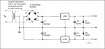
I figured my easiest answer as I already have a toroidal transformer with 2 X 18v secondaries was to .....
Join the secondaries to give me a ground line and to full wave rectify the two ends of the secondaries figuring it will give me around +/-25v. ( 18v X 1.414)
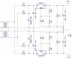
Now on to this +/-25v bus hang both positive and negative 3 pin regulators in
5v, 9v, 12v, and 15v flavours

I found a circuit online showing this done with a pair of Pos and Neg 12v regulators which hopefully I can attach the pic to this post , as I have some questions about it
In the diagram, what do diodes D5 and D6 do and are they neccesary.
I can see that C3 and C4 are a good idea to put on the output of every pair of regulators that I use but do I need C1 and C2 on the input of every pair of regulators too or is it enough to just have C1 and C2 on the output of the bridge rectifier and share them between all the regulators ?

Lastly, am I ok to use 4 pairs of regulators on this one transformer/rectifier output ?

BTW I can see that the voltage of some of the Caps in the picture need changing to suit my voltages

Thanks for your help
Don
 

Attachments

BeanieBots

Moderator
Your idea should be OK.
Only one set of large caps required but put a smaller value close to the input of each regulator.
You might like to consider running the lower voltage regulators from the output of the higher voltage ones. That will help keep package dissipation down.

IMHO, D5 & D6 are not required.
 

donrecardo

Senior Member
Your idea should be OK.
Only one set of large caps required but put a smaller value close to the input of each regulator.
You might like to consider running the lower voltage regulators from the output of the higher voltage ones. That will help keep package dissipation down.

IMHO, D5 & D6 are not required.

Thanks Beanie

Your opinion is good enough for me

Cheers
Don
 

Andrew Cowan

Senior Member
I'd imagine it is mainly for logic/low level stuff - the 1A given by the 78xx and 79xx series, coupled with a 50W+ or so transformer would be fine for most op-amp based experementation (not including audio amplifiers).

A
 

Grogster

Senior Member
I agreen with BeanieBots, and the "Pre-regulator" is a very good idea for the 5v rails, even if they only take about 100mA or so. As said - keeps the heat dissipation down, but the current from the 5v regulators must be factored into the current ability of the 12v regulators, as they are the ones suppling the 5v regulators if you see what we mean...

The heat dissipation of each regulator is found simply by P=(Vin-Vout) x I
P is power in watts, and I is current in amps.

So, if you have 100mA current on the 5v regulators, with 25v in, the calculation becomes:

P=(25-5) x 0.1
P=20 x 0.1
P=2 watts

...so the 5v regulators will want to dissipate 2W of heat for only 100mA of output current at 5v with a 25v input - this will require a reasonable heatsink to get rid of.

I also agree with donrecardo - how can you design a PSU without knowing what the output current requirements are?

Perhaps you could consider a beefy 12v regulator arrangement(such as 7812/7912's with pass-transistors), and daisy-chain the 7805/7905 etc regulators from it. The beefy 12v regulator would carry the total current of all the sub-regulators plus the 12v rails aswell.
 

donrecardo

Senior Member
I'd imagine it is mainly for logic/low level stuff - the 1A given by the 78xx and 79xx series, coupled with a 50W+ or so transformer would be fine for most op-amp based experementation (not including audio amplifiers).

A
You hit it on the head Andrew.

I want to learn about OP Amps as I have never used one before .
I needed to make a few split rail supplies for simple experiments with the selection of Op Amps that I have but I will never be drawing very much current.

I did follow the reasoning behind powering the 5v regulators from the 12v
supply so as to reduce the dissipation , and intend to follow that advice.

Thanks to all that helped
Have a good Xmas
Don
 

marks

Senior Member
have also been looking at op amps lately on the net lol
bought one of those ph probes
but didnt realise you couldnt even get a reading on a digital meter !
Was going to use the classic +-15v linear supply which i started drawing
but now decided to look at single rail op amps
so will be looking at designing something different.

D5 and D6 diodes provide protective output clamp
(where output voltage would tend to reverse should one supply fail).
protection for the opamps not the regulator
 

Attachments

Last edited:

matherp

Senior Member
Don

If you have separate secondaries you don't need the 79xx versions of the regulators. Just set up two separate supplies with separate diode bridges and connect the + side of the "bottom" supply to the gnd of the "top" one.

Also, if you are only ever going to use a maximum of two voltage pairs, one of which is +/-5V then you could use switched trimmer resistors across the 1.25v reference of a couple of LM317 to give the higher voltages and then 7805s to give the lower. This will save on board real estate and heatsinks

Best regards

Peter
 

Jaguarjoe

Senior Member
Most 3 pin regulators die when the output voltage is greater than the input voltage. This is current 'reversing' into the regulator because the output capacitors still have a charge on them when the input is lost and they discharge back through the regulator.
A diode is normally placed between the input and output of the regulator to prevent this.
I still don't see D5/6 doing anything.
 

BeanieBots

Moderator
@Marks,
pH probes can have impedances in 100Mohm region.:eek:
You can't use "any old op-amp" with them. You need one with exceptionally low bias current and exceptionally high input impedance.
A fingerprint on your PCB will reduce the reading by half.
Take GREAT care with PCB cleanliness and use "guarding" techniques.

Why the variable regulators?
Either use 'standard' 7815 & 7915, or as suggested by matherp, as you have seperate supplies, you could use two of the same type of regulator.
 

Jaguarjoe

Senior Member
Here's a femtoamp input op-amp:

http://www.analog.com/static/imported-files/data_sheets/AD549.pdf

The datasheet has lots of good information about working with such low current.

Years ago we made op amps almost like this out of discrete components to make charge amplifiers. These op amps did not have any resistors for Rin or Rf, they had polystyrene capacitors instead. The ceramic range select rotary switch was dipped in silicone fluid and placed in a vacuum chamber to eliminate even the slightest bit of moisture.

Unfortunatly, as input current goes down, cost goes up. These are about $40 each.
 

marks

Senior Member
Thanks BeanieBots , Jaguarjoe for your great input
i,m still at the crazy idea stage yet for that 1 its still evolving lol
no parts yet for that one maybe next year .
proberly just build a simple amp meter first.
at the moment in the process of making a project board
as i,m still using a breadboard for my projects which is not ideal
sorry a bit slow at doing stuff still in the learning process .

I,m thinking of using a wire wrapping ic socket for the op amp when i do the ph meter
and not have it on the circuit board at all.
 

Attachments

Jaguarjoe

Senior Member
I,m thinking of using a wire wrapping ic socket for the op amp when i do the ph meter
and not have it on the circuit board at all.
Actually, the only pin on that IC that requires special treatment is the non-inverting input on the first op-amp. Bend that pin out of the way and solder the shielded wire directly to it. That way the other pins can be soldered to the PCB just like normal.
 
Top