Power Mosfet

MartinM57

Moderator
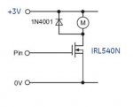
Possibly, but you shouldn't think like that/use a MOSFET like that.

IRL540N are designed to be used as "low side switches" i.e.
Supply -> load -> drain
PICAXE to gate
Source to ground

...and when you supply voltage to the gate from the PICAXE, the MOSFET conducts (i.e. the drain-source resistance goes down - called Rds in the data sheets) and your load now has a current path to ground so it can now light/flash/engage/turn/whatever.

Thinking that the drain voltage will appear on the source is maybe not the right road to go down, as you will then be tempted to drive your load with that source voltage - and you have thus made your MOSFET a high side switch...which will not work (with a IRL540N, anyway)
 

mproia

Member
Hi MartinM57, I believe what you describes is what I am doing.

Here is a similar picture to what I have.

IRL540N.JPG

Is this how you explained it? If so should I expect 3 Volts to pass through the motor or will there be a loss of voltage? When I hook the motor up to the power rail and the ground it moves quite fast. When i switch it on using the mosfet it does not turn as quickly.

Thanks.
 

MartinM57

Moderator
Exactly that.

Being a pedantic soul, you need to use the right terminology - voltage doesn't pass through the motor...but current does.

What voltage are you running the PICAXE with? What voltage do you measure at the gate with your multimeter when the PICAXE is outputting a high logic level?
 

premelec

Senior Member
Running the PX at 4.9v and only 2v to the gate?? Where did that 2.9 volts go? The gate is a very high impedance if things are normal... suggest disconnecting MOSFET and measuring PX output voltage... and if you are using same supply for motor and FET then measure the supply voltage while motor running... see if you've got voltage loss there etc...
 

mproia

Member
Okay looked over my breadboard and the outout pin from the picaxe to the mosfet had an LED on it (so I could visually see it on as a check) and the other end of the LED lead attached to ground. I did not think that this would be a problem. I took off the LED and the voltage was ~4.9 volts.
 

John West

Senior Member
A typical LED, fully iluminated, will draw just about all of the current a PICAXE can source. Also, the typical LED will drop about 2 volts across it when it's on. That means the PICAXE output voltage at the top of the diode will be held down at 2 volts.

If you add a resistor in series with the LED to limit its current to 10mA or so (try a 330 Ohm one,) and to drop the difference between the 5 volts and the 2 volts, you may still be able to run both circuits on the PICAXE output. The LED will be a bit dimmer, but will still light, and the resistor will drop about 3 volts, while the LED will drop about 2 volts, leaving the FET gate voltage high enough for the FET to be fully turned on. The FET really needs to see nearly all of that 5 volts in order for its internal resistance to drop to fractional ohms of resistance so the motor will get full power.

As is, it requires specially designed MOSFET's in order to have the gates turn on fully at voltages as low as 5 V. Most of them require closer to 8 to 10 volts for full turn-on.
 
Top