Its Shrunk !
I spent quite a while doing some real on-air decoding tests, rather than just looking at a scope trace, and came to the conclusion that simple is best. The NE567 manages quite well on its own.
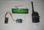
The left picture is the decoder working on-air decoding morse at 60WPM. It uses a 08M2, and can work at 15WPM or 60WPM, selected at power up. The output is to a AXE133Y 18M2 driver (with modified code), shown connected to a 20x2 LCD. The incoming Morse scrolls up from the bottom line. A switch freezes the display on the last 40 characers.
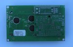
The PCB shown on the right could be spilt into the 08M2 decoder PCB (to use with AXE133Y) and a small PCB with a SOIC 18F25K22 that could also drive the LCD\OLED, emulating the AXE133Y code. Kept together the PCB was intended to mount on the back of the LCD display.
Code and circuit diagram to follow.
I spent quite a while doing some real on-air decoding tests, rather than just looking at a scope trace, and came to the conclusion that simple is best. The NE567 manages quite well on its own.
The left picture is the decoder working on-air decoding morse at 60WPM. It uses a 08M2, and can work at 15WPM or 60WPM, selected at power up. The output is to a AXE133Y 18M2 driver (with modified code), shown connected to a 20x2 LCD. The incoming Morse scrolls up from the bottom line. A switch freezes the display on the last 40 characers.
The PCB shown on the right could be spilt into the 08M2 decoder PCB (to use with AXE133Y) and a small PCB with a SOIC 18F25K22 that could also drive the LCD\OLED, emulating the AXE133Y code. Kept together the PCB was intended to mount on the back of the LCD display.
Code and circuit diagram to follow.
Attachments
-
 78 KB Views: 286
 -
 68.7 KB Views: 213