Port C.2 not working

sid

Senior Member
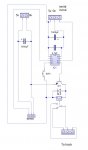
I've been working on a circuit to control a servo and a relay for what seems like months now and have got to the stage were the circuit and code has been refined and work 99% as I want it to
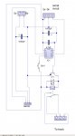
When the circuit starts up for the first time c.3 is used to set the parameters of the servo movement left and right and these are written to memory, however on subsequent start ups the program remembers where everything was with the exception of the relay which is controlled by port c.2

Code:
#picaxe 08m2	;servo & relay pcb v2.0


start:
read 1,b2
read 2,b3
read 3,b4
read 4,b5
if b5=0 then goto program
if b5=1 then goto preoperate
goto start


;=================================================================================
;programing mode
;===============

program:
disconnect
b1=150			
pulsout c.4,b1	;centre
pause 1000

do
if pinc.3=1 then gosub check
if pinc.3=1 then goto cont1
pause 35
toggle c.1
loop

check:
pause 1000
return

cont1:
do
high c.1
if pinc.3=0 then goto cont2
loop

cont2:
low c.1
pause 1000
high c.1
do 
pulsout c.4,b1
pause 100
inc b1
loop until pinc.3=1
b2=b1
write 1,b2

low c.1
pause 1000
high c.1

do			
pulsout c.4,b1
pause 100
dec b1
loop until pinc.3=1
b3=b1
write 2,b3

b4=0
b5=1
write 3,b4
write 4,b5
reconnect
low c.1

B6=1		;TELLS THE CONTROL PANEL WHICH SERVO IT'S WORKING ON
serout c.1,n1200_4, ("END",b6)

goto operate


;================================================================================

;=============================================================
;normal operation
;=============================================================

preoperate:

if b4=0 then relay 
if b4=1 then operate

relay:
pause 1000
high c.2


operate:
serin [1000,reprogram],c.1,n1200_4,("SERVO1"),b7
if b7=0 and b4=0 then goto left
if b7=0 and b4=1 then goto sendend
if b7=1 and b4=1 then goto right
if b7=1 and b4=0 then goto sendend 
goto operate

reprogram:
if pinc.3=1 then goto program
goto operate

left:
b4=1
write 3,b4
low c.2
for b0 = b3 to b2
pulsout c.4,b0
pause 50
next b0
goto sendend


right:
b4=0
write 3,b4
high c.2
for b0 = b2 to b3 step-1
pulsout c.4,b0
pause 50
next b0
goto sendend

SENDEND:
b8=1
serout c.1,n1200_4, ("END",b8)
goto operate
On the first start up c.2 works as it should but on subsequent start ups it doesn't.
If I run the code through the simulator ,it works
If I change the code at the pre operate section to read
Code:
preoperate:

if b4=0 then relay1
if b4=1 then relay2

relay1:
do
toggle c.2
pause 500
loop

relay2:
do
toggle c.2
pause 2000
loop
Then c.2 works fine, switching the relay fast or slow depending on the value of b4

So I know the hardware's good and I know the software's good, but I can't for the life of me see why C.2 won't work having read the value of b4 on subsequent start ups. I've even put a meter across 0v and pin C.2 but the output stays 0.

Can a fresh pair of eyes see what I'm obviously missing
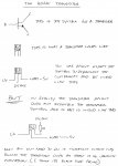
 

nick12ab

Senior Member
Code:
#picaxe 08m2	;servo & relay pcb v2.0


start:
read 1,b2
read 2,b3
read 3,b4
read 4,b5
if b5=0 then goto program
if b5=1 then goto preoperate
goto start


;=================================================================================
;programing mode
;===============

program:
disconnect
b1=150			
pulsout c.4,b1	;centre
pause 1000
.......................................
AARRRGGGHHHH! No white spacing! And it's spaghetti code! Before I have to read that, have you got a decoupling capacitor?
 

sid

Senior Member
Capture.JPG

Please see attached diagram

All pins have 10k resistors to earth omitted for clarity, likewise the programming circuit
Two separate regulated power supplies, one for the axe and one for the servo

Also the two 0v are connected, but I forgot to show this on the diagram
 

srnet

Senior Member
Indeed, not really much point in posting a 'redacted' circuit diagram.

Dont you keep a copy of the real circuit diagram ?
 

sid

Senior Member
Indeed, not really much point in posting a 'redacted' circuit diagram.

Dont you keep a copy of the real circuit diagram ?
1. Nick12ab :As per the original post the transistor is switched by c.2 on the initial start up and continues to work fine, I have used transistors without 1k resistors several times all to good effect, so I would say the need for a 1k resistor is not necessary
2. MartinM57: when I say all pins I mean all pins with the exception of pins 1&8 but I assumed this was just obvious
3. Srnet : I don't do circuit diagrams as a rule, I create circuits using breadboard and then pcb wizard, so have no need for a diagram, and I was trying to rectify a mistake for the benefit of anyone reading so they didn't point out the obvious, so if you can't say anything constructive please refrain from offering me advice!
 

nick12ab

Senior Member
1. Nick12ab :As per the original post the transistor is switched by c.2 on the initial start up and continues to work fine, I have used transistors without 1k resistors several times all to good effect, so I would say the need for a 1k resistor is not necessary
If the base current of the transistor allows for more than 20mA to be 'drawn' from the PICAXE pin then there's a good chance that you'll damage the PICAXE. Just use a 1k resistor and see if that fixes the problem.

2. MartinM57: when I say all pins I mean all pins with the exception of pins 1&8 but I assumed this was just obvious
It is if you know it. However the rest of us don't necessarily know it and also if you say that, you might have missed the omission of an important resistor.

if you can't say anything constructive please refrain from offering me advice!
No-one's posted non-constructive information. That 'redacted' circuit diagram is pointless.
 

sid

Senior Member
servo and relay diagram.JPG

OK point taken,
Full diagram attached
I will try adding a 1k resistor between c.2 and the tranistor
 

westaust55

Moderator
Even a 1 kOhm resistor may not be right.
You need to look at the datasheet for the transistor you are using plus the repaly coil ohms or current draw and ascertain some parameters rather than guessing that no resistor or 1 kOhm is required. In the past I had found resistors up to 3.3 kOhm can be acceptable rather than driving a PICAXE output at higher current than necessary as there are overall limits for the entire PICAXE current which may determine lower current per IO than 20 mA.

For some idea on the math the calculate the resistor value:
See post 4 here: http://www.picaxeforum.co.uk/showthread.php?19011-Need-some-advice-re-resistors-and-LED-s
See post 6 here: http://www.picaxeforum.co.uk/showthread.php?16426-Possibly-stupid-question
 

bluejets

Senior Member
Why all the 10k resistors to ground..??

Cap on ser in socket ,1000uf back to front

47uf seems high for decoupling if thats what it is, normally only 0.1uf

no base resistor on transistor

diagram difficult to follow, not impossible just not the norm in circuit diagrams and hard to get an overall picture.
 
Last edited:

mrburnette

Senior Member
@Sid:

I know you said everything works in simulator, but in looking over the code i found several "goto" jumps out of Do-Loop constructs. If is OK to do gosub from within the loop, but it is better practice to use "exit" to break out of the Do-Loop. It may be that the real chip is having some stack issues and if so, really weird things could happen.

IF a gosub is not used by any other subroutine call, then bring that code inside the IF/then/else statements to eliminate the subroutine. When you are ready to leave the Do-Loop, use the command EXIT ... this can be inside a If/then/else logic nesting if necessary.

The other thing you can do is write a short program that just loads the variables from eeprom and then debugs them to the console. Remember, if you use #no_data then the eeprom will remain the way it did when the master program failed!

Good luck,

-Ray
 

MartinM57

Moderator
I will try adding a 1k resistor between c.2 and the tranistor
probably prudent to have a spare transistor to hand as well - and maybe even a spare PICAXE - direct connection of an output to the base of a pnp transistor will probably blow the transistor base-emitter junction and may have damaged the PICAXE output pin.
 

inglewoodpete

Senior Member
I will try adding a 1k resistor between c.2 and the tranistor
A resistor between c.2 and the base of the transistor in mandatory. It's not a case of "trying it". You may already have damaged the PICAXE and/or the transistor. Edit: beaten by Martin - I took too long!

It is conventional to draw a circuit with the +ve rail across the top and the 0v (or common) rail across the bottom. Your current drawing takes an inordinate amount of time to understand.
 

srnet

Senior Member
Srnet : I don't do circuit diagrams as a rule, I create circuits using breadboard and then pcb wizard, so have no need for a diagram, and I was trying to rectify a mistake for the benefit of anyone reading so they didn't point out the obvious, so if you can't say anything constructive please refrain from offering me advice!
That was constructive advice, especially if you are expecting others to give you advice for free !!!

As for not having the need for a circuit diagram, then I would suggest its obvious you do, especially if you want advice for free.
 

sid

Senior Member
If I write...
Code:
start:
high c.2
goto start
C.2 will not switch, and a meter across C.2 and v0 shows no life
However, if I write...
Code:
start:
high c.2
pause 1000
low c.2
pause 1000
goto start
or
Code:
start:
do
toggle c.2
pause 1000
loop
Then C.2 happily switch's on/off

Again with my program where C.2 is apart of a section of code, C.2 switch's
Code:
right:
b4=0
write 3,b4
high c.2
for b0 = b2 to b3 step-1
pulsout c.4,b0
pause 50
next b0
goto sendend
But when C.2 is a stand alone instruction it doesn't work
Code:
relay:
pause 1000
high c.2
Not with standing all the other issues with my circuit diagrams and lack of resistors and my knowledge of electronics in general, is there a reason why C.2 won't work when working as a stand alone instruction within this circuit?
 

hippy

Ex-Staff (retired)
Not with standing all the other issues with my circuit diagrams and lack of resistors and my knowledge of electronics in general, is there a reason why C.2 won't work when working as a stand alone instruction within this circuit?
There would seem to be be little reason for a HIGH C.2 not to work when a HIGH C.2 / LOW C.2 does.

I would guess that there is something external to the PICAXE causing the problem, you are measuring C.2 in the wrong place or in the wrong way, or your measuring equipment is not accurately revealing what is actually happening.

How the C.2 pin should behave as output when not connected to anything is defined and should be easy to verify, but how it may behave when connected to something can depend on what it is connected to and how.
 

Paix

Senior Member
Best I don't give advice in case it is misinterpreted. Non-standard diagrams can and do obfuscate.

Disconnect everything from pin C.2 whilst taking measurements to verify the correct operation of the PICAXE chip. Once that is sorted and the chip understood to be operating correctly then you can connect it back and continue to debug the circuitry.

1. Can you confirm that the zero volts connections between the two connectors in the upper left and upper centre part of the of the diagram are connected together. It is not at all obvious from your diagram.

2. The diode across the relay is the wrong way around and so likely to cause problems if it is other than a diagram error.

3. The 10k resistor between transistor base and ground will probably lift the base into conduction if C.2 is disconnected. I think that Nick12ab was suggesting in post #5 that a 1k resistor should be placed in series, between the C.2 pin and the transistor base connection. The object being to limit the base current as well as adding protection for the C.2 pin. The 10k base bias resistor is not required. The C.2 pin is either high or low and so provides all the bias required.
 

bluejets

Senior Member
2. The diode across the relay is the wrong way around and so likely to cause problems if it is other than a diagram error.
Diagram is confusing you also just like me originally....diode is ok, however, that whopping 1000uF cap on the supply back-to-front should cause a smoke-up shortly.
 

Paix

Senior Member
Fair cop Bluejets, but I guess that you can see where and why I got it wrong! Once I rotated the section of the diagram the obvious struck me, SImilarly with Ol Smokey if conventions had been observed then it would have jumped out instantly at almost anyone. Just tilting the head to change the perspective does strange things with the grey cells.

G284.png

The diode in the bad version was actually my diagram reading error, aided and abetted by the original diagram layout which I interpreted wrongly.
 

Attachments

sid

Senior Member
BD681 and relay.jpgimg016.jpg

I've found the problem,
Its my inability to be able to read a component pin-out and then connect said component properly.
What confused me was that even though the transistor was connected incorrectly it did actually sometimes work!
My apology's to all for my stupidity and my thanks to all for advice given.
I've drawn two advice sheets so others might avoid my mistake.

And one last thing, yes the circuit does operate far better with a 1k resistor between the picaxe and the transistor
 
Last edited:

Paix

Senior Member
I bought this book around 1976 and it's archived on line now. Affectionately known as TITS it's a bit dated but will cover a lot of common devices that are still in use today.

http://ia700804.us.archive.org/15/items/TowersInternationalTransistorSelector/Towers-TowersInternationalTransistorSelector.pdf


G285a.png

It used to be that transistor pinouts were as viewed from the bottom and ICs from the top. Not sure where the definitive source of pinouts is available these days as I think that the Towers' bible has passed into history? Probably online.

I must have used the book at least twice in earnest :) but considered it to be part of my education and helped my understanding. Obviously the paper version was easier to navigate than the pdf, but select a couple of common transistors and use the appendixes for the lead (pin) outs.

Glad that everything is working good for you now Sid. The feedback was/is appreciated.
 

bluejets

Senior Member
View attachment 11841View attachment 11840

I've found the problem,
Its my inability to be able to read a component pin-out and then connect said component properly.
What confused me was that even though the transistor was connected incorrectly it did actually sometimes work!
My apology's to all for my stupidity and my thanks to all for advice given.
I've drawn two advice sheets so others might avoid my mistake.

And one last thing, yes the circuit does operate far better with a 1k resistor between the picaxe and the transistor
Hence, the need for a drawn-up circuit diagram. I usually include any pinouts of components such as transistors,regulators,etc also.

Resistor in the base I would find a mandatory addition, but I am curious how you ascertain that the transistor is working "far better" now with the resistor. After all, it's operating a small relay, either it operates or it doesn't. Did you take some current readings..?
 

AllyCat

Senior Member
What confused me was that even though the transistor was connected incorrectly it did actually sometimes work!

I've drawn two advice sheets so others might avoid my mistake.
Hi,

Thanks for taking the trouble to report your findings which should help others, or us to help others.

However, strictly, you should have put a diode across the relay coil. An inductor (such as a relay coil) can generate a large voltage "spike" when switched off, which can damage a transistor and/or the PICaxe.

The reason why "power" transistors normally have the collector as the middle pin is because the physical construction mounts the collector directly onto the metal "tab", and it is sensible to connect the tab to the middle pin (so either can be used).

As to why it "sometimes worked", probably a case of "two wrongs making a right". I believe that you connected the transistor such that the "collector-base diode" joined the PICaxe output pin to the relay. Normally the "base resistor" (which you wrongly omitted) would limit the current , but in your case you effectively connected the PICaxe pin to the relay via just a diode. In practice, the relay might be sensitive enough to just operate directly from the current available from a PICaxe. But the relay would operate when the output was driven LOW instead of the intended High.

Cheers, Alan.
 
Top