rq3
Senior Member
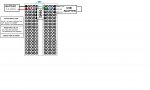
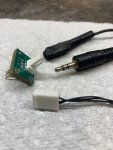
For quite some time I have used standard Pogo pins for programming. The photos show the AXE-027 to Molex KK to Pogo pin sequence. This gives me the option of using the "standard" AXE-027 stereo jack, a 0.1 inch center Molex KK connector, or no connector at all.
The Pogo pins fit a 0.025 or 0.029 inch plated through hole on a printed circuit board, or a Protoboard or Perfboard for prototyping. Saves space and a connector, and has never failed me. I commonly include the fooprint for the Pogo adapter on my PCB layouts, so the Gerber files include it for anyone duplicating the board.
I use these pins:

 www.adafruit.com
They say the spring loaded needles are 0.030 inches in diameter. They're not. They're 0.025 inches in diameter. I generally just poke the pins through plated through holes on the PCB and don't try to make spring pressure contact.
One good mod would be to add an offset fourth pin connected to ground, so that the pin pattern is "polarized". That way you have less chance of reversing the Pogo sequence and connecting SEROUT to ground. Of course, I've never done that (cough, cough), but the Picaxe survived.
The Pogo pins fit a 0.025 or 0.029 inch plated through hole on a printed circuit board, or a Protoboard or Perfboard for prototyping. Saves space and a connector, and has never failed me. I commonly include the fooprint for the Pogo adapter on my PCB layouts, so the Gerber files include it for anyone duplicating the board.
I use these pins:
Pogo Pins "Needle Head" (10 pack)
Pogo pins are little spring-loaded contacts, very handy for making jigs, or making momentary (but electrically solid) contacts. We use them by the dozen for making programming and testing ...
www.adafruit.com
They say the spring loaded needles are 0.030 inches in diameter. They're not. They're 0.025 inches in diameter. I generally just poke the pins through plated through holes on the PCB and don't try to make spring pressure contact.
One good mod would be to add an offset fourth pin connected to ground, so that the pin pattern is "polarized". That way you have less chance of reversing the Pogo sequence and connecting SEROUT to ground. Of course, I've never done that (cough, cough), but the Picaxe survived.
Attachments
-
 384.1 KB Views: 28
 -
 378.2 KB Views: 27
Last edited:
")