Please look at schematic and help me figure out why its not working

Noidea

New Member
Hi there,

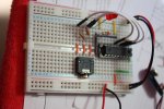
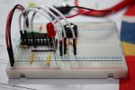
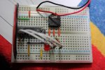
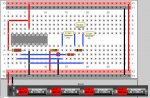
with much help from many memebers and recent posts from WestAust55/Hippy (to name a few) I have made my first breadboard ... problem is it does not work.

This is so I can start to program and use the picaxe 18, with reset which is not listed.

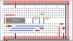
I have listed here the schematic from <Pebbles>;
Wire||207|187|21||11|#FF0000|7|11|||
IC||227|270|1||U?|||DIP18|IC||DIP18_1
Wire||342|77|21||11|#FF0000|6|11|||
Wire||209|185|11||11|#FF0000|5|11|||
Wire||342|379|21||11|#000000|6|11|||
Wire||317|432|11||11|#FDFF00|6|11|||
Resistor|4700|211|371|1|Resistor|R?||3||IC||
Wire||477|379|21||11|#FF0000|5|11|||
LED|0|520|379|4|LED|LED?|1|||IC||led_14
Wire||531|434|21||11|#000000|4|11|||
Resistor|330|481|373|1|Resistor|R?||1||IC||
Wire||558|269|21||11|#3253FF|3|11|||
Wire||692|269|21||11|#3253FF|3|11|||
Wire||638|269|21||11|#3253FF|3|11|||
Resistor|10000|642|373|1|Resistor|R?||1||IC||
Resistor|22000|589|401|1|Resistor|R?||1||IC||
Wire||344|460|11||11|#3253FF|13|11|||
Wire||290|405|11||11|#3253FF|11|11|||
Wire||263|432|11||11|#3253FF|11|11|||
Wire||207|269|21||11|#FF0000|3|11|||
Wire||989|77|21||11|#FF0000|16|11|||
Wire||962|104|21||11|#000000|16|11|||
Miscell||206|595|1||XX?||1|11|Miscell||misc_11
Wire||234|544|21||11|#000000|2|11|||
Wire||207|516|21||11|#FF0000|3|11|||
Note||565|258|1||||||3.5 jack connector (TC)||NOTEPAD_1
Note||701|261|1||||||3.5 jack connector (A)||NOTEPAD_1
Note||641|204|1||||||3.5 jack connector (O)||NOTEPAD_1
IC||227|270|1||U?|||PICAXE18|IC||PICAXE18_1
BREADBOARDSTYLE=BB11

Please see attachment, thank you all for your help and patience with and absolute Newb!!

(oo) NoIdea (oo)
 

Attachments

BeanieBots

Moderator
I've not double checked your layout but a quick glance looks OK.
However, I have found that the pins on the 3.5mm jack are too short to reach down and make contact with the strip-board connectors.
Try pushing down hard on the connector socket when doing the download.

Better still, solder some wires onto it and push them into the breadboard or get yourself proto adaptor for it.
 

Dippy

Moderator
I've had exactly the same issues as BB re: socket and did exactly as he did.

A) Images are great, are you sure your real-life breadboard conenctions are the same?
2) Have you tried just 3 x AA?
iii) "It does not work" - Umm can you clarify? More details? What connection tests have you done?
It's like me saying "My car won't start, Why not?" ;)
 

SilentScreamer

Senior Member
If you solder wires directly to a jack socket be careful not to damage the socket with the heat (took me a long time to work it out when I did it:p).
 

Dippy

Moderator
Are you using the 'standard' cheapie PICAXE jack socket?
If so, don't forget to solder the back pins in pairs to be safe.
 

Andrew Cowan

Senior Member
Definitly a photo. High quality would be good, but a mobile-phone-camera is better than my cloudy crystal ball.

I've soldered header pins onto a download socket before, to make it fit into a breadboard.

A
 

Noidea

New Member
Dear All,

Thanks for the suggestions and comments.

I am attempting to build a template for all future projects, the aim is to make a complete board, this is part one, with part two coming after this. Part two will be a power regulator circuit for 12v - 8v. The finished product as mentioned will be my template. Other aims are to be as compact as possible and as neat as possible.

When I say it does not work, when trying to upload a simple test prog

[ high 0]
[low 1]
[high 2]

I get the standard error message of your cable is not connected, not powered, or the picaxe needs to be reset..... so sill no idea.

Dippy, Beaniebots and SilentScreamer,
Thanks for the suggestion, I have used some jumper leads and aligator clips just to test and still no joy.

Eclectic,
Sure no worries please see attached.

Dippy,
As you will see (hopefully) from the pics is that the board is wired exactly the same, with one addition that I could not draw on the schematic program ... you will see a wire (purple) coming from off pin 5, this then goes down and under picaxe, this will be the reset (awaiting delivery tomorrow) switch which will follow of this to switch and then to negative on right hand side of board.

Again any and all comments would be appreciated.

(oo) NoIdea (oo)
 

Attachments

BeanieBots

Moderator
Can't be 100% sure but the resistor from pin 3 looks like it goes up to the set of holes just above the PICAXE, but then where?
If it's floating, that would explain a lot.

What is the green wire for (top right of last picture)?
One end is pin14, can't see the other end.
 
Last edited:

manuka

Senior Member
Several thoughts from "down under".
* IMHO it'd be much better to start with a 08M for setup verification. Have you experience with these?
* Is that LED & 330 Ohm just to show power is available? Does it light OK?
* Are you running off 4 x alkaline AAs? If so (& they're fresh) this may exceed the 18X supply limits!
* The 18X can be inserted directly into a breadboard. Forget the IC socket - it's contacts may be an issue.
* Does this 18X actually work elsewhere? Is it new?
* Is your programming cable known to normally work?
* Have you selected the correct PICAXE from the programming editor?
* Failing a "made for it" AXE029 BB programming adapter, consider direct insertion of the programming cable into the BB with a simple DIY adapter. This will be simpler & more reliable than at present- no on board jack needed.

The PEBBLE 2.3 layout shown here (to match yours) is perhaps more lucid. However check instead the ~2003 era layout shown => http://www.picaxe.orconhosting.net.nz/keyb18xa.jpg, as this may be more versatile. Stan
Code:
IC||227|270|1||U?|||DIP18|IC||DIP18_1
Wire||209|240|11||11|#FF0000|5|11|||
Wire||342|462|21||11|#000000|3|11|||
Wire||317|432|11||11|#FDFF00|6|11|||
Resistor|4700|211|371|1|Resistor|R?||3||IC||
Wire||881|379|21||11|#FF0000|5|11|||
LED|0|924|379|4|LED|LED?|1|||IC||led_14
Wire||935|462|21||11|#000000|3|11|||
Resistor|330|885|346|1|Resistor|R?||1||IC||
Wire||558|269|21||11|#3253FF|3|11|||
Wire||692|269|21||11|#3253FF|3|11|||
Wire||638|269|21||11|#3253FF|3|11|||
Resistor|10000|642|401|1|Resistor|R?||1||IC||
Resistor|22000|589|428|1|Resistor|R?||1||IC||
Wire||344|377|11||11|#3253FF|13|11|||
Wire||290|405|11||11|#3253FF|11|11|||
Wire||263|432|11||11|#3253FF|11|11|||
Wire||207|269|21||11|#FF0000|3|11|||
Wire||989|77|21||11|#FF0000|16|11|||
Wire||962|104|21||11|#000000|16|11|||
Miscell||206|595|1||XX?||1|11|Miscell||misc_11
Wire||234|544|21||11|#000000|2|11|||
Wire||207|516|21||11|#FF0000|3|11|||
Note||565|258|1||||||3.5 jack connector (TC)||NOTEPAD_1
Note||701|261|1||||||3.5 jack connector (A)||NOTEPAD_1
Note||641|204|1||||||3.5 jack connector (O)||NOTEPAD_1
IC||227|270|1|PICAXE-18X|U?|||PICAXE18|IC||PICAXE18_1
Wire||342|77|21||11|#FF0000|3|11|||
BREADBOARDSTYLE=BB11
 

Attachments

Last edited:
Top