Hi,
Resistor calculations basically require Ohm's Law which defines a Resistance value (R) from the Voltage (V) applied across and Current (I) which flows through the Resistor. To avoid using lots of zeros, it's useful for us to employ "consistent units", for example of Volts , milliAmps and kOhms. The normal formula is
R = V / I , which can be re-arranged as
V = I * R or
I = V / R , depending on which value we're trying to calculate. Similarly, the power (rating) P is given by multiplying the Voltage by the Current i.e.
P = V * I (with a "consistent unit" of milliWatts) , which can again be arranged in alternative forms as
P = I2 * R or
P = V2 / R .
I've never actually used a
Nixie Tube, but I believe they have similar characteristics to a
Neon Lamp, i.e. as described by Wikipedia:
"Each cathode can be made to glow in the characteristic neon red-orange color by applying about 170 volts DC at a few milliamperes between a cathode and the anode. The current limiting is normally implemented as an anode resistor of a few tens of thousands of ohms. Nixies exhibit negative resistance and will maintain their glow at typically 20 V to 30 V below the strike voltage. "
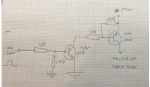
So if we assume that your 130 volts is sufficient to "strike" the tube, then the Anode voltage should fall to about 100 volts and the current in the (PNP's) emitter resistor will be
I = V / R = 30 /15k
= 2 mA. That current exits the PNP through two terminals, the Base and the Collector (to the Anode) and as the transistor is being used as a switch (in this case), then E, B and C will all be at about 100 volts (above "Earth"). Thus the current in the base resistor (if 10k) would be 100 / 10k = 10 mA, but that is more than is available through the emitter, so we have a problem.

Another way to consider it is that the PNP Base-Emitter junction is a forward biassed diode (which drops about 600 mV) so we have a potential divider of 15k + 10k across the (130v) supply rail. Thus the transistor terminals are at about 130v * 10k / (15k + 10k) = 52 volts, which is highly unlikely to be sufficient to allow the Nixie Anode/Digit to strike.
So it looks to me as if the "middle" resistor needs to be
at least 100k. That will pull approximately 1 mA through the PNP base (turning it on) but leaves only another ~1 mA to flow from the emitter through the collector to the Anode. Probably a higher resistance would be better, or alternatively, the 15k emitter resistor needs to be reduced to say 10k, even for an Anode current of 2 mA. Note that if several anodes are all connected to the same 15k resistor via one or more diodes (which appear to serve no useful purpose) then once any Anode is struck, then there will be insufficient voltage to activate any other digit. Therefore any illuminated digit must be switched off, before another digit can be lit.
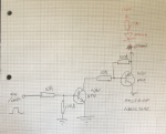
Addendum: Whilst using a "common" 15k resistor may give some economy of component numbers, personally I would have used a configuration more like that shown in the link from hippy, i.e. a separate "Anode" (current limiting) resistor in each
collector of the PNPs and a Base current-limiting resistor of up to
400k. That will still give a base current of around 300 uA, easily sufficient for a collector current of up to a few mA.
Cheers, Alan.