Picaxe28X2 to WiFly to COSM , anyone?
- Thread starter Simmicht
- Start date
mark.duyvesteyn
Member
I'm not sure but would love to know also!
I've not heard of that thing before, but it sure looks interesting. Being pin-compatible with xbee any picaxe-xbee hardware should work.
Writing a program for that kind of thing will not be as straightforward, but a simple data-sending web client should not be too hard. With the help of the WiFly manual making a http client connection doesn't look too hard.. There are examples available at least for arduino on how to send data to the cosm server, those will help with the syntax once you get the thing otherwise running with your axe.
Writing a program for that kind of thing will not be as straightforward, but a simple data-sending web client should not be too hard. With the help of the WiFly manual making a http client connection doesn't look too hard.. There are examples available at least for arduino on how to send data to the cosm server, those will help with the syntax once you get the thing otherwise running with your axe.
It is not clear, but the WiFly unit as an Arduino shield is using a serial port to communicate with the Adruino, although most units use SPI bus. You would need to study the Wifly.h library and convert each command into a PICAXE equivalent, which would not be that difficult to do - time aside.
I think using an Ardunio would be easier.
I use the Ethernet shield to upload data to my web site and it wourks fine, very reliable and easy to use. Here's some development code an as example:
It's a bit messy but it gives you the idea of what's possible, whether it's via a wired or wireless connection, in this example I was sending, BMP08 air pressure, CPU temp, time, etc - playing really...
BTW using the PICAXE NET board would be even easier to use and more versatile IMO because it supports tags.
Code:
void listenForEthernetClients() {
  // listen for incoming clients
  EthernetClient client = server.available();
  if (client) {
    Serial.println("Got a client");
    // an http request ends with a blank line
    boolean currentLineIsBlank = true;
    while (client.connected()){
      if (client.available()) {
        char c = client.read();
        // if you've gotten to the end of the line (received a newline
        // character) and the line is blank, the http request has ended,
        // so you can send a reply
        if (c == '\n' && currentLineIsBlank) {
          // send a standard http response header
//         client.println("HTTP/1.1 200 OK");
         client.println("<!DOCTYPE html PUBLIC \"-//W3C//DTD HTML 4.01//EN\" \"http://www.w3.org/TR/html4/strict.dtd\">");
         client.println("<html xmlns=\"http://www.w3.org/1999/xhtml\">");
         client.println("<meta http-equiv=\"refresh\" content=\"10\">");
         client.println("<meta http-equiv=\"Content-Type\" content=\"text/html; charset=utf-8\" / >");
         client.println("<PRE>");
         //print the current readings, in HTML format:
         client.print("<body>");
         client.print("<body bgcolor=\"#CAE1FF\">");
         client.println("*** ARDUINO Webserver *** (c) G6EJD 2012");
         client.println("Currently serving out Temperature, Air Pressure, Distance and Time");
         client.println("Sensors: BMP085 Temp and Pressure, Ultrasonic HC-SR04 for Distance and DS1307 for time");
         client.println();
         client.print("Air Temperature : ");
         client.print(temperature);
         client.print("°C");
         client.println();
         client.print("CPU Temperature : ");
         client.print(GetTemp());
         client.print("°C");
         client.println();
         client.print("   Air Pressure : ");
         client.print(float(int((pressure+545)/10))/10);
         client.print(" mB");
         client.println();
         float duration;                     // Define the variable we will use to store the pulse duration
         digitalWrite(trigPin, HIGH);        // Set the trigPin high, start of pulse to get module working
         delayMicroseconds(10);              // Wait 10 uS
         digitalWrite(trigPin, LOW);         // Set the trigPin low, module will now send a pulse
         duration = pulseIn(echoPin, HIGH);  // Read the pulse length from the module
         client.print("       Distance : ");
         client.print(float(int(duration / 61*10))/10); // Send the distance in cm to the serial port
         client.println(" cm");
         DateTime now = RTC.now();
         client.print("   Current Time : ");
         if (now.day() < 10) { client.print("0"); }
         client.print(now.day(), DEC);
         client.print('/');
         if (now.month() < 10) { client.print("0"); }
         client.print(now.month(), DEC);
         client.print('/');
         client.print(now.year(), DEC);
         client.print(' ');
         if (now.hour() < 10) { client.print("0"); }
         client.print(now.hour(), DEC);
         client.print(':');
         if (now.minute() < 10) { client.print("0"); }
         client.print(now.minute(), DEC);
         client.print(':');
         if (now.second() < 10) { client.print("0"); }
         client.print(now.second(), DEC);
         client.println();
         client.println("<BR />");
         client.println("</PRE>");
         client.println("</body>");
         client.println("</html>");
         break;
         }
        if (c == '\n') {
        // you're starting a new line
        currentLineIsBlank = true;
        }
        else if (c != '\r') {
        // you've gotten a character on the current line
        currentLineIsBlank = false;
        }
      }
    }
    // give the web browser time to receive the data
    delay(1);
    // close the connection:
    client.stop();
  }
}The Wifly from roving networks is very easy to use it, can be configured from a pc across your WiFi network or set up in adhoc mode and configured from an iPod iPad or pc. Once configured it can basically send and receive serial data over tcp or udp and can be used to post data to a specific server, it can also be used as a serial bridge with two of them. They work great with picaxe I have used them in a few projects including android /iPhone control you only need to understand serial com's to make them work reliably with picaxe and they only require a 3.3v regulated supply rgb status led and a few external resistors to operate in there most basic state. The pdf files from roving are readily available on the site and need studying to get your config right but that's the hardest part to that module.
WiFly = A WiFi to serial device. 3.3v +- 10% (but found it a bit flaky at 3.0v) and a peak current draw of around 180mA during transmit.
Easiest to set up from the serial side. Serial is pretty standard stuff. However it does not really support any fancy hardware handshaking and is fixed at N81 but the speed can be changed.
Have one surplus to requirements and available at a reasonable price if if anyone is interested - PM me if so.
Easiest to set up from the serial side. Serial is pretty standard stuff. However it does not really support any fancy hardware handshaking and is fixed at N81 but the speed can be changed.
Have one surplus to requirements and available at a reasonable price if if anyone is interested - PM me if so.
BCJKiwi: Is this surplus unit the original WiFly or their new version ?
@ Manuka
This is not a Sparkfun A***no shield.
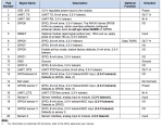
It is the actual WiFly RN-XV module as shipped by roving networks http://dlnmh9ip6v2uc.cloudfront.net/datasheets/Wireless/WiFi/WiFly-RN-XV-DS.pdf
Was purchased new via nicegear a few weeks ago and now surplus to requirements (project changed).
This is not a Sparkfun A***no shield.
It is the actual WiFly RN-XV module as shipped by roving networks http://dlnmh9ip6v2uc.cloudfront.net/datasheets/Wireless/WiFi/WiFly-RN-XV-DS.pdf
Was purchased new via nicegear a few weeks ago and now surplus to requirements (project changed).
I got one of these RN-XV modules last week.
I am trying to get some serial communication from the picaxe to an ftp server on my local network.
Its simple to setup the unit through a serial lead, I used the same shield that are used for zigbee, that has the serial to usb chip plus the 3.3v regulated supply.
I have yet to get by picaxe to sucessfully communicate with the ftp server even though I had no trouble via the terminal.
I guess I must be going about it all wrong, below is my code.
Any ideas?
I am trying to get some serial communication from the picaxe to an ftp server on my local network.
Its simple to setup the unit through a serial lead, I used the same shield that are used for zigbee, that has the serial to usb chip plus the 3.3v regulated supply.
I have yet to get by picaxe to sucessfully communicate with the ftp server even though I had no trouble via the terminal.
I guess I must be going about it all wrong, below is my code.
Code:
ftp:
	wait 5
	serout c.4, T2400, ("ftp put data.txt")
	wait 3
	serout c.4, T2400, ("test text")
	wait 10
	debug
goto ftpThats correct, the username, password and target ip address are stored in the modules config so the command as I have works fine from a serial console.
Not seeing any attempt at connection on the ftp server log so I'm wondering will I need to do some type of port sniffing to see whats going on or am I way off the mark with my sample connection program.
The below opens the connection to the ftp server then opens a new file "data.txt"
Then will write to the above file the following and the connection will automatically close after a timeout idle period.
Not seeing any attempt at connection on the ftp server log so I'm wondering will I need to do some type of port sniffing to see whats going on or am I way off the mark with my sample connection program.
The below opens the connection to the ftp server then opens a new file "data.txt"
Code:
ftp put data.txt
Code:
test textDoes the serial lead also use CTS/RTS? If so try linking those two pins together when using the PICAXE.Its simple to setup the unit through a serial lead, I used the same shield that are used for zigbee, that has the serial to usb chip plus the 3.3v regulated supply.
Looked at the data sheet and pins 12 and 16 are for uart rts/cts on the wifly. I briefly tried bridging these with a bit of wire when I had the unit connected to the picaxe. No joy. Should I connect one of these to a separate pin output and pull it high at the same time as sending data to the serial? I am just going out on a limb there with that statement as I thought I saw reference to someone doing something similar maybe however it was when they were using a different type of shield for serial connection. Any ideas?
Just had a look at the schematic for the xbee-explorer you indicated that you were using.
It has an FTDI chip on it. It is the serial in that chip that you need to consider.
Working circuit for another device that only requires TXD/RXD and GND (like the picaxe serial) has a number of connections on the FTDI end to sort this issue.
CTS connected to RTS Leg 11 to 3 on FTDI
&
DTR connected to DSR & DCD Leg 2 to 9 & 10.
I would try just CTS--RTS first.
Also the WiFly does not expect these to be connected so hopefully the board allows you to connect these at the FTDI without that connection also being seen by the WiFly.
If not then there may be more work to do in the WiFly to cope with that configuration.
Just had a look at the schematic for the xbee-explorer you indicated that you were using.
It has an FTDI chip on it. It is the serial in that chip that you need to consider.
Working circuit for another device that only requires TXD/RXD and GND (like the picaxe serial) has a number of connections on the FTDI end to sort this issue.
CTS connected to RTS Leg 11 to 3 on FTDI
&
DTR connected to DSR & DCD Leg 2 to 9 & 10.
I would try just CTS--RTS first.
Also the WiFly does not expect these to be connected so hopefully the board allows you to connect these at the FTDI without that connection also being seen by the WiFly.
If not then there may be more work to do in the WiFly to cope with that configuration.
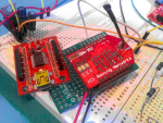
Thanks for your response, just to clarify I am attempting to connect directly to the Wifly unit from the Picaxe I don't have an FTDI chip in the mix here as is on the adaptor zigbee board.
See attached photos which show that now I am just connecting Vcc Gnd and take the serial connection from Picaxe pin direct to Wifly.
On the left of the current header shield you can see the picture of the zigbee shield which as you correctly pointed out has the FTDI serial chip.
The second photo attached is a shot from the datasheet for the Wifly which gives its pin outs.
Funnily enough I do see the data light flashing on the Wifly unit so it must be receiving some sort of signal from the Picaxe.
Also I have ran tcpdump on the target server and the only traffic I see looks like multicast udp stuff, no trace of any tcp attempt.
I anyone could explain a little more what step I should try next it would be appreciated.
Well, you provided a link to the xbee explorer so I assumed that was what was being connected to.
You need 4 connections to the WiFly - 1. Power (3.3V +- 10%. I found 3V was not stable),
2.RX
3.TX. this thing draws around 180mA when transmirring so if you are sharing power with the picaxe there may be some issues if the supply is not good. (I scoped this and found the current leapt around all over the place when running continuously).
4. common gnd to the PicAxe
RX and TX to TX and RX on the Picaxe and common gnd.
So is the issue with the serial, or with how to send via the network.
Have you verified that the network connection is good? there are a few conmmands you can use to check signal strength, find acces points etc that will verify that.
After that I am not much help (if I have been of any so far!).
I think maybe I have overlooked something on the Picaxe programming side. I have verified network as much as possible as I am able to ping the unit from the FTP server and see multicast packets coming from the unit on the FTP server.
My power supply should be good. I am using a 5v rail for picaxe and have powered the Wifly via 3v3 reg off the same 5v rail.
My power supply should be good. I am using a 5v rail for picaxe and have powered the Wifly via 3v3 reg off the same 5v rail.
So how are you connecting the 5V PICAXE signal to the 3V3 Wifly?. I am using a 5v rail for picaxe and have powered the Wifly via 3v3 reg off the same 5v rail.
Start again with a simple as possible circuit.
1) Same 3V3 power supply connected to both PICAXE and Wifly
2) PICAXE TX pin connected to Wifly RX pin
3) PICAXE RX pin connected to Wifly TX pin
4) Make sure baud rate (4800, 9600 etc) and baud rate polarity (T4800, N4800 etc) match what the WiFly expects.
So how are you connecting the 5V PICAXE signal to the 3V3 Wifly?Well spotted but I am actually connecting the pin via 4 IN4001 s in series to give me a volt drop to near enough 3.5 v measured.
hippy
Ex-Staff (retired)
Two potential problems with that; 3.5V would seem to be above the maximum voltage allowed on the WiFly inputs, and it makes the signal 'open emitter'; 5V output will pull the input high, but 0V output will leave the input floating.I am actually connecting the pin via 4 IN4001 s in series to give me a volt drop to near enough 3.5 v measured.
Using one diode turned the other way, adding a pull-up to 3V3, making it 'open collector' would arguably be a better option but running the PICAXE at 3V3 with direct connections would be the best option. At least for getting things working.
Looks like I'm beat on this for the moment there must be something else going on in the Wifly that I don't understand.
I took your advise and rand the Picaxe on the same 3v3 rail as the Wifly, also I used an 10k pull down on the data pin.
See attached scope traces from both N and T serout.


I took your advise and rand the Picaxe on the same 3v3 rail as the Wifly, also I used an 10k pull down on the data pin.
See attached scope traces from both N and T serout.
Ok, I see now where at least one major issue is now.
I connected again using the usb/serial shield to minicom terminal, of course then I realised that I was after skipping one vital step when connecting the Picaxe directly.
The terminal console session with the wifly unit needs to be initiated with "$$$" which sends it into command mode.
After I changed my code a little I was able to get some communication to the ftp server from the Picaxe directly, the issue now is that this is hit and miss, I need to find a way to listen for the return command from the Wifly before proceeding to the next serout command.
I am using a low baud rate of 2400 so I think the serout/serin will do me currently, does anyone have a link to some example which demonstrates this?
Below is my current code and in the commented out lines you can see the responses which I need to wait on from the Wifly before executing the next step:
Code:
	symbol counter= w0
	counter = 1
	high c.4
	serout c.4, T2400, ("exit")
wifly:
	wait 10
	serout c.4, T2400, ("$$$")
	;CMD
	wait 1
	serout c.4, T2400, ("ftp put data.txt",counter)
	;*OPEN*
	wait 1
	serout c.4, T2400, ("test text")
	;*CLOS*
	wait 1
	serout c.4, T2400, ("exit")
	;EXIT
	counter = counter + 1
	debug
goto wiflyIf you are not interested in processing the returned data, and know how many letters the reply is, just serin the number of letters into a dummy variable.
Code:
    symbol counter= w0
    counter = 1
    high c.4
    serout c.4, T2400, ("exit")
wifly:
    wait 10
    serout c.4, T2400, ("$$$")
    ;CMD
    serin c.x, T2400, b1,b1,b1
    serout c.4, T2400, ("ftp put data.txt",counter)
    ;*OPEN*
    serin c.x, T2400, b1,b1,b1,b1,b1,b1
etc.Thanks Technical for your response, I have tried something like you suggested but using a qualifier on the serin which I think is correct if I want to listen for a specific response.
I'm not sure now is my issue the fact that the Wifly is responding too quickly for the Picaxe, ie. that it returns a response before the Picaxe has time to listen, is this possible?
I'm using a 14M2 with default settings.
I have now modified my code to look as follows, from the debug screen shot it can be seen that the program hangs waiting on the first serin command.
See also the screen shot from the scope capture which shows the TX in blue from Picaxe and RX in red, note the 20ms resolution.
Code:
	symbol counter= b0
	symbol letter1 = b1
	symbol letter2 = b2
	symbol letter3 = b3
	symbol letter4 = b4
	symbol letter5 = b5
	symbol letter6 = b6
	symbol place = b7
	counter = 1
	high c.4
	place = 0
	debug
	wait 20
	goto wifly

resetletter:

		letter1 = 0
		letter2 = 0
		letter3 = 0
		letter4 = 0
		letter5 = 0
		letter6 = 0
		return

wifly:
	place = 1
	debug
	wait 5
	place = 2
	debug
	serout c.4, T2400, ("$$$")
	;CMD
	place = 3
	debug
	serin c.3, T2400, ("CMD"), letter1,letter2,letter3
	place = 4
	debug
	wait 5
	;goto resetletter
	;serout c.4, T2400, ("ftp put data.txt",counter)
	;*OPEN*
	;serin c.3, T2400, b10,b10,b10,b10,b10,b10
	;serout c.4, T2400, ("test text")
	;*CLOS*
	;serin c.3, T2400, b10,b10,b10,b10,b10,b10
	serout c.4, T2400, ("exit")
	;EXIT
	serin c.3, T2400, ("EXIT"), letter1,letter2,letter3,letter4
	counter = counter + 1
	wait 5
	;goto resetletter
goto wiflyIt is way too slow because you have a debug before the serin. Remove it, as you are currently effectively trying to transmit a load of data (debug) before the serin can start!
Also this line looks for 6 characters "CMDxxx" - which is probably not what you intended
serin c.3, T2400, ("CMD"), letter1,letter2,letter3
try
serin c.3, T2400, ("CMD")
Also this line looks for 6 characters "CMDxxx" - which is probably not what you intended
serin c.3, T2400, ("CMD"), letter1,letter2,letter3
try
serin c.3, T2400, ("CMD")
Great I have gotten further and I a able to catch the "CMD" being returned I have verified this by subbing the CMD in the serin with just 3 variables and then setting a debug after the serin.
I am wondering is there some other way of sending an "Enter" key press other then using "lf" or "cr" as I now believe the Wifly unit does not correctly
process the next command which is to open the FTP connection to the server.
I have done testing on this with the wifly connected to the USB/serial adaptor and an "Enter" key press is required before the command is processed.
Anyone got any ideas?
hippy
Ex-Staff (retired)
Not sure how you mean by some other way, but it did draw attention to the fact it seems you are not sending any 'enter' to the module from your PICAXE program and that would likely be required. That 'enter' is likely to be CR, LF or CR then LF. The datasheet or user manual should indicate which.I am wondering is there some other way of sending an "Enter" key press other then using "lf" or "cr" as I now believe the Wifly unit does not correctly process the next command which is to open the FTP connection to the server.
Added: It's CR.
http://dlnmh9ip6v2uc.cloudfront.net/datasheets/Wireless/WiFi/WiFly-RN-UM.pdf
Page 6 paraphrased ...
To enter command mode $$$ must be sent. There is no carriage return (<cr>) after the $$$.
While in command mode, the device will accept ASCII bytes as commands. Each command ends with a carriage return <cr>.
Last edited:

Ok, I have finally got this working reasonably well, It works mostly however at times it just seems to hang after it enters command mode as if perhaps the PICAXE has missed the return "CMD" signal.
I can probably overcome this by adding a time out and breaking out of the loop?
EDIT:
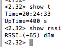
I have another issue which I believe is due to the Wifly returning multiple lines when a command is sent, see attached screen shot which show the results returned for time, is it possible to parse this information with the PICAXE?
I can probably overcome this by adding a time out and breaking out of the loop?
EDIT:
I have another issue which I believe is due to the Wifly returning multiple lines when a command is sent, see attached screen shot which show the results returned for time, is it possible to parse this information with the PICAXE?
Code:
	setfreq m32
	symbol counter= b0
	counter = 1
	high c.4
	wait 60
	wait 60
	goto wifly


wifly:
	serout c.4, T9600_32, ("$$$")
	;CMD
	serin c.3, T9600_32, ("CMD")
	wait 16
	serout c.4, T9600_32, ("ftp put ",#counter,"data.txt",cr)
	;*OPEN*
	serin c.3, T9600_32, ("*OPEN*")
	serout c.4, T9600_32, ("Lots of info line 1",lf,"Lots of info line 2",lf)
	;*CLOS*
	serin c.3, T9600_32, ("*CLOS*")
	wait 16
	serout c.4, T9600_32, ("exit",cr)
	;EXIT
	serin c.3, T9600_32, ("EXIT")
	wait 60
	wait 60
	counter = counter + 1
	goto wifly
Last edited:
hippy
Ex-Staff (retired)
It could be that the WiFly is responding sooner than the PICAXE is ready to receive its reply. It is possible to timeout if no reply is received, but if you do that you don't know if entering command mode was successful or not which makes it difficult to decide how to proceed.
The ideal solution is to use an X2 and high-speed background receive which will always catch any reply sent no matter how soon after a command is issued. This will also allow data returned that is of variable length to be more easily parsed.
The ideal solution is to use an X2 and high-speed background receive which will always catch any reply sent no matter how soon after a command is issued. This will also allow data returned that is of variable length to be more easily parsed.
I was thinking that may be root cause alright as it is intermittent.It could be that the WiFly is responding sooner than the PICAXE is ready to receive its reply. It is possible to timeout if no reply is received, but if you do that you don't know if entering command mode was successful or not which makes it difficult to decide how to proceed.
The ideal solution is to use an X2 and high-speed background receive which will always catch any reply sent no matter how soon after a command is issued. This will also allow data returned that is of variable length to be more easily parsed.
I 'am attempting to convert my previous code to use with a 20x2 but I am having difficulty understanding how I set the hersin command first to listen before I send the hserout to the WiFly unit.
I have cobbled together the below piece of code from examples I have seen but I don't think it will work correctly.
How do I "background" the hersin command while allowing the rest of the program to proceed with the hersout?
Code:
waitcmd:
	hsersetup B9600_32, %00
	;Wait for "CMD" to be returned and then proceed with the next step
	hserin [ 1000, waitcmd] ,0,3, ("C")
	ptr = 0
	b1=@ptrinc : if b1 = "M" then waitcmd
	b1=@ptrinc : if b1 = "D" then waitcmd
	goto wifly

wifly:
        ;Send the command to enter AT mode on the WiFly
hserout 0, ("$$$")Ok, I think this is correct as now I am able to process the returned "CMD, but I am unsure if the hersin is definetlly listening in the background?
I'm sure I have set bit 0 correctly to 0 in the hsersetup:
But am I correctly calling the backgrounded hserin data with the following command or is it just standalone from the backgrounded receiced data?
I'm sure I have set bit 0 correctly to 0 in the hsersetup:
Code:
hsersetup B9600_32, %000
Code:
wifly1:

	;CMD
	hserin [ 1000,  wifly1] ,0,3, ("C")
	ptr = 0
	b2=@ptrinc : if b2 <>"M" then wifly1
	b2=@ptrinc : if b2 <>"D" then wifly1
	goto wifly2
Code:
wifly:
	;bit0 - background receive serial data to the scratchpad (not M2 parts)
	;bit1 - invert serial output data (0 = ‘T’, 1 = “N”)
	;bit 2 - invert serial input data (0 = “T”, 1 = “N”)
	;bit 3 - disable hserout (1 = hserout pin normal i/o)
	;bit 4 - disable hserin (1 = hserin pin normal i/o)
	hsersetup B9600_32, %000

	hserout 0, ("$$$")
	goto wifly1

wifly1:

	;CMD
	hserin [ 1000,  wifly1] ,0,3, ("C")
	ptr = 0
	b2=@ptrinc : if b2 <>"M" then wifly1
	b2=@ptrinc : if b2 <>"D" then wifly1
	goto wifly2


wifly2:
	success = 1
	debug
hippy
Ex-Staff (retired)
You are not using HSERIN in background receive mode. Rather you are using HSERIN similar to how you were using SERIN after SEROUT earlier, though I would guess it is taking advantage of the double buffering of the serial receive buffer.Ok, I think this is correct as now I am able to process the returned "CMD, but I am unsure if the hersin is definetlly listening in the background?
I'm sure I have set bit 0 correctly to 0 in the hsersetup:
Code:hsersetup B9600_32, %000
For full background receive you need %001 in the HSERSETUP, but if it's working then what you have would seem to be acceptable.
Thanks hippy.
So will I be ok with my existing example once I change the hsersetup to %001?
If not do you know of any good examples that you could point me to?
I guess there is a couple of concepts that I need to get to grips with here in order to convert my existing code to a full fail safe method.
So will I be ok with my existing example once I change the hsersetup to %001?
If not do you know of any good examples that you could point me to?
I guess there is a couple of concepts that I need to get to grips with here in order to convert my existing code to a full fail safe method.
hippy
Ex-Staff (retired)
One would normally use background receive or the HSERIN command not both so there are potential problems. I was really only clarifying that you weren't using background receive. If what you have works then stick with that.So will I be ok with my existing example once I change the hsersetup to %001?
If you want to use full background receive you have to enable it, issue your HSEROUT, then check if the scratchpad contains what you would expect, wait until it does or timeout if it doesn't. I doubt there are any tutorials on how to do all that but you might find some other program that does similar. I'd develop it on a 'works or grinds to a halt' basis, then work out how to rescue it from grinding to a halt.
I'd continue with using HSERIN for now because it seems the important goal is getting it to send messages. If everything works ( as it would be expected to ) then you can code for that, get the project working per se, then return to making it more robust if that's even needed.