Picaxe Satellite PongSat NLSE-2

kranenborg

Senior Member
Here I present a proposed design of the successor of the PongSat-18X NLSE-1 near-space satellite ( http://www.picaxeforum.co.uk/showthread.php?t=9236 ).

It appears that we will get a ticket by JPAerospace for a planned flight over a thunderstorm (date yet unknown, the flight will be somewhat higher than the previous flight if possible), so that made me decide that the NLSE-2 will become a PongSat dedictated to measuring electrostatic potential in the atmosphere. I want to use the 18M2 Touch facilities to try to estimate the electric field distribution as a function of elevation. I have no idea whether the Touch functionality will be sensitive enough for it, but with a large sensor surface (essentially the whole pingpong ball outer surface) it is worth a try. In each step the change in capacity is recorded as a change in atmospheric potential.

The Pongsat's outside surface will be wrapped with aluminum and connected with a Touch input and thus act as a electric field sensor. Subsequently the whole surface will be wrapped in plastic in order to avoid static electricity problems during handling by me or others.

Apart from this new feature the same sensor types as with NLSE-1 will be applied, ie. temperature, tilt, vibration, and optical sensors for measurement of light intensity.

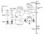
Here is the initial scheme:


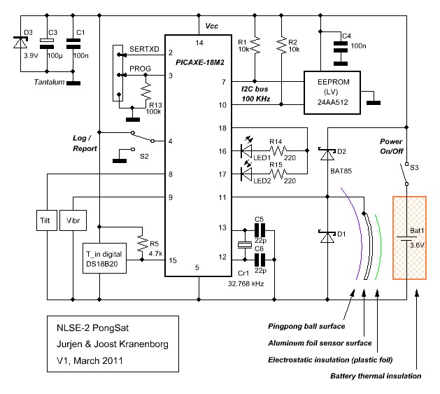
I imagine that the sensor voltage could sometimes be out of the 0 - Vcc range, so I decided to add a few safety measures by adding shunt diodes D1, D2 at the sensor input, as well as zener Diode D3

Could this design potentially work for measuring atmospheric electrostatic potential? Any opinions/suggestions are most welcome.

/Jurjen
 
Last edited:

BeanieBots

Moderator
I think D1 might cause you some problems.
Although there will be plenty of 'volts' from the static level, I would fear that the PIC S/H capacitance will soak up most if not all of any available electrons. Even the BAT85 might give a problem at such ultra low currents.

I'd suggest the use of a special high impedance op-amp to buffer your static sensor. You could then add known capacitance and not need to worry about protecting the PICAXE input or whatever effects the ADC S/H circuit will have on your readings.
 
Last edited:

womai

Senior Member
I doubt this will work. The protection diodes have non-negligible leakage current even in reverse direction. That will swamp any change in charge there may be. (the surface of a table tennis ball will have less than ~1nF of capacitance). You really need a VERY high impedance sensor - probably somewhere in the 100 MOhm range. There may be suitable op-amps around that could pull this off - connect the sensor to the + input and wire the op-amp in a non-inverting configuration. Alternatively a high-quality instrumentation amplifier (a different tyoe of op-amp circuit) could work. Just removing the protection diodes won't help because the Picaxe has a very similar arrangement of protection diodes internally.

To test any sebsor you come up with you can use something that can be charged statically - e.g. suitable piece of plastic foil - and bring it near to the sensor. That's a very safe method and can produce field strengths of thousands of Volts per meter - similar to what you would see in a thunderstorm.

In any case my old offer to do the printed circuit board still stands if you are interested. If you use SMD components you could pack a whole lot more circuitry in the limited space.

Wolfgang
 

womai

Senior Member
Here are some circuit ideas for electrometers. Huge input impedance is absolutely crucial. Note that this also means the surfaces of the components and the printed circuit board must be spotlessly clean, no grease from your fingers or similar. You'll need to bath the assembly in alcohol before it is ready for its flight.

http://www.datasheetcatalog.org/datasheet/analogdevices/139322066ad546.pdf

http://www.seekic.com/forum/22_circuit_diagram/21632_OPAMP_ELECTROMETER.html

http://amasci.com/electrom/sas51p1.html#Electro
 

kranenborg

Senior Member
Thanks Beaniebots and Womai, I am now convinced that a buffering circuit with extremely high impedance for the sensor input is needed, and therefore the Touch capabilities will not be needed (ADC instead). I will gladly consider Womai's offer for the circuit board as this will definitely be needed to pack everything into the pingpong ball.
I will now dive more in the links that Womai provided regarding high-impedance amplifiers

Regards,
Jurjen
http://www.kranenborg.org/electronics
 

womai

Senior Member
Regarding the test method - I meant it's safe for humans. Not so safe for sensitive electronics, so be careful to avoid ESD damage. Probably best to test it on a separate fixture with just the sensor circuit, not the one that will fly into space.
 

NXTreme

Senior Member
Remember, it only needs to work once. Just so long as it does its job well, and functions the way up and down, right? :eek:
 
Last edited:

womai

Senior Member
No, it got to work twice. The first time is when you test it. You wouldn't want to send the thing up and down and then discover what you built has never worked and will never work :) Actually, with the time between flights measured in years, you want to test it many times under different conditions before sending it up there. And even then things can go wrong (just ask NASA :)
 

MFB

Senior Member
I was interested to read that you plan to fly over a thunderstorm and was wondering if it would be possible to look for sprites (lighting from the cloud tops to space) using a video camera. I have been playing with a ‘spy’ camera that is extensively described at http://www.chucklohr.com/808/

As you can see from this site the board is very small and light when removed from the case. If it could be flown, the main difficulty in capturing a sprite image would be their short duration but could a lucky video frame do it?
 

kranenborg

Senior Member
@MFB: The sprites that appear to occur quite regularly are actually JPA's motivation for this flight, as John Powell (JPAerospace) wrote to me:

One of our projects is to fly a vehicle into a sprite. We need to go a bit higher but I think we can do it. That would be a great upper atmosphere electrical storm to fly your PongSat into.
Now nobody really knows what the energy density of a sprite is, so I guess that to my PongSat the effect of (accidentally) flying through or close to a sprite could be anything between not detecting it and destroyed circuitry, but that is the price of research ... . I even thought of detecting and triggering a camera by the pongsat, but it may well be that normal lightning will give a similar trigger too.

Maybe we can get JPAerospace interested in the use of such a camera, but I could imagine that they have considered something similar themselves, given their motivation as quoted. I will send them a mail with the question

/Jurjen
 

kranenborg

Senior Member
Regarding instrumentation amplifiers, would the MAX4460 variable-gain instrumentation amplifier be suitable? It is available in an SO-8 or SOT-6 package, has programmable gain (I could use a digital pot for programmable control) and runs on 2.8V .It has the following characteristics:

-1pA (typ) Input Bias Current
-100µV Input Offset Voltage
700µA Supply Current
±0.1% Gain Error
2.5MHz Gain-Bandwidth Product
18nV/ Input-Referred Noise

obtained via the following link: http://www.maxim-ic.com/datasheet/index.mvp/id/3249
Would it be suitable for the job?

/Jurjen
 

kranenborg

Senior Member
Charge sensor high-impedance interface proposal

After the previous discussions I dived into the wonderful world of (instrumentation) opamps and came up with a proposed circuit design for the very high impedance charge sensor (aluminum foil on the outside surface of the pingpong ball) connection to the Picaxe (changed to 20X2. SMD version). I would like to have some feedback on whether my proposal is an improvement. The circuit is in the attachment (details like decoupling caps will be added later), let me explain my thoughts behind it.

Circuit functioning:

The sensor is first connected to an instrumentation opamp (OP1, chosen because of its very high input impedance of 2 giga-ohm), then the signal is amplified (OP3, with software-controlled amplification through reostat R3) and fed into an ADC input of the picaxe. In order to allow a swing in both positive and negative voltage directions, OP2 and C4 provides a low-impedance artificial ground to OP1 and OP3 based on the output of the MAX6018 Voltage Reference (used sucessfully in the NLSE-1, and its temperature dependency of operation is well documented, contrary to the PIC voltage refs).

There are a few boundary conditions that influenced the design:

1. The unknown voltage swing range of the sensor (positive and negative, may exceed the GND-Vcc range. This is caused by the unknown capacitance of the sensor, as well as the unknown field strength of the atmosphere). This made me decide to do differential measurements instead, by periodically setting the charge level corresponding to an accurately defined Vref of 1.2V. In this way it should be possible to register any voltage swing during a certain period, and the total swing can be integrated from the total measurement set. The instrumentation opamp is wired in such a way that its output is at Vref as well in the case S1 is closed (Vref at + input), such that it has some headroom to swing in both directions. Switch S1 is what I propose to use to charge the sensor. S1 must have a very high impedance as well, so maybe a mini-reedrelais should be used here (any semiconductor switch usable instead?)

2. Low battery voltage (3.6V, but may be lower in cold conditions): this made me look for an opamp that has very good output rail-to-rail capabilities (at low output load), which the MCP6242 double opamp has (50mV at low load, particularly relevant for OP3)

3. It would be nice to estimate the capacity of the aluminum foil sensor, in order to be able to estimate the field strength. Therefore I added the optional switch S2 which allows to add a known parallel capacitance and then measure the voltage drop and thus estimate the capacity. Additionally, S2/C1 provide for hardware attenuation of the signal if needed.

Would this be a proper hardware setup for the sensor?

Thanks,
Jurjen
 

Attachments

Last edited:

womai

Senior Member
I'd be concerned about leakage through C1 - it's effective resistance will be far below the 2 GOhm of the opamp input.
 

Dippy

Moderator
So this would be an isolated device (vehicle) measuring an electric field?
Where is the reference?
I would have thought that you do need a known leakage to calculate the charge?

Just allowing a surface to charge up seems odd to me.
I can't get my head around that, but then again I'm thick and I need to mow the lawn. :eek:
 

kranenborg

Senior Member
@Womai, maybe then this part should be removed (or be part of a prototype version only)

@Dippy: The reference is Vref itself (or GND, since Vref - GND is constant), but both are only defined locally during the flight and ultimately with respect to earth potential at launch time & location. By closing S1 at earth ground level first and then doing this at regular intervals my idea is that in this way the potential change of the sensor can be recorded each time at the end of the interval, then the switch is closed directly afterwards to define the start of a new interval. Thus the total potential change wrt. to lauch situation can be determined by adding the interval changes. Is my reasoning flawed here? I do not see exactly why a leakage current is needed here. A (small) current will flow through R1 each time S1 is closed in order to restore the potential of the sensor.

Are there solid-state alternatives for S1 (and S2) available, or should the total circuit be revised to get rid of them? Reed swithes do have some power consumption and lead to some power line disturbance ...

/Jurjen
 
Last edited:

MFB

Senior Member
Avoiding the effects of leakage current could be a major challenge for this application. Even when developing low current/high impedance measurement circuitry for operation in a laboratory environment I found problems due to board leakage etc. A good solution was to use a National Semiconductor LM331 precision V-F converter (into PICAXE count input) to provide a wide dynamic range and bending the input pin and other sensitive components off the board. Nat Semi give some very useful information on the choice of components in their LM331 application note.

PS. Any feedback from John Powell?
 

John West

Senior Member
I find this difficult to fully grasp, so please read this as mere conjecture.

It seems to me that the goal of determining charge "potential" does indeed need a fixed reference. If I understand correctly what you are intending to do, then each time you "dump" the charge by shorting the inputs, you are effectively storing a new charge reference level. But you don't really know in an absolute sense what that charge level is, even referenced to that at your launch point.

It seems to me that without quite a sophisticated circuit, (something not likely to fit into a pongsat) that about all you could determine is whether the outside charge is increasing or decreasing.

Additionally, I'm not sure a pongsat sized circuit can be built that can handle the extreme voltages involved on its input.

However, I have a physicist friend who has done such research for the U.S. air force regarding airplane static electrical charges as they move from place to place among storm clouds, and will bring it up with him for comment. I'll report back if I learn anything of use.
 

Dippy

Moderator
That's what I struggle with too wrt measuirng a field using that design of electronics.
I could understand it reflecting a change in electric field strength but not absolute mesaurement.
I could also understand it if you used a physical property such as electron force or movement or velocity.
Or even the PD between 2 isolated/insulated electrodes.
Or even some kind of switching/moving detection.
But I can't get a handle on this design.
Is there an electric Hall-alike effect equiv sensor?

I'd have to engage brain for more than 5 minutes so I'll retire and wait for John's friend to nail it :( - I've probably got the wrong end of this static stick :)
 

kranenborg

Senior Member
Hello,

Thanks for the responses so far.

What I am after is not so much an accurate atmospheric potential measurement (using an electrometer: http://en.wikipedia.org/wiki/Electrometer ) but am happy with a simpler circuit detecting changes in atmospheric charge (i.e. an electroscope: http://en.wikipedia.org/wiki/Electroscope ), altough it would still be nice if in the latter case there is a linear relation between measured charge change and the atmospheric potential change.

I think that MFB hits the nail on the head by mentioning "low-current / high impedance": it is either to keep the high impedance level (which is apparently very difficult to realize) or to measure small current changes (on which I have the feeling that this might still be simpler given the MTouch functionality and having read more background material on the PIC functionality behind it. In particular the following links on the CTMU - Charge Time Measurement Unit - : http://techtrain.microchip.com/webseminars/documents/CTMU_101408.pdf and http://ww1.microchip.com/downloads/en/DeviceDoc/39724a.pdf provide much more information about how the touch functionality is implemented, it is interesting reading).

I will first do some homework myself by investigating a somewhat simplified problem, namely the case of a sphere (grounded via a given resistance) in a changing electrical field (constant potential change, the atmospheric gradient is of the order 100V / m and the climb velocity of the pongsat will be approx 4m / s, giving 400V / s as a first estimate), with V (t=0) = 0 for all potentials.

@ John West: I am very interested in your friend's ideas & experiences.

@ MFB: No reply yet from John Powell, will ask again

/Jurjen
 
Last edited:

Dippy

Moderator
I suggest you try out this circuit in a fully isolated way before committing it.
I still can't get my head around how your device will measure relatively or absolutely. It may measure something but unless you can prove your theory you are simply stuck on the result that something changed by some amount.

An electric field only exists as a potential gradient between point A and point B. Often you need a great supply of electrons from a lump called Earth.

My poor old addled brain compares your design with a dicky-bird happily sitting on an elelctric cable strung between two pylons.
Surely you should be measuring a PD , microcurrent flow between 2 points of different potential , or some kind of differential sensing or the effect of the EF on particles? (e.g. electrons...Movement, force or whatever).
I hope JW's friend can put me out of my misery.:confused:

Anyway, I suggest you search to see what the Big Boys do.
Good luck with it. Sounds very interesting.
 

John West

Senior Member
I had only a moment the other day to talk to my physicist friend, so this isn't much info, and I may have it wrong because he immediately began speaking in math functions that were quite beyond my poor secondary school education.

If I have it right, the technique is not much more than the creation of a Leyden Jar, with the measuring system mounted within, (so the circuit resides in a Faraday Cage,) using the physical shape to create a capacitor that can have its outside/inside surface charge differential properly measured as the "jar" floats through the air. The inside surface of the "jar" acts as the measurement reference while the outside adds or subtracts electrons as the device floats through the sky.

In my opinion, the pongsat may work to measure the charge in this way if properly constructed as it already has the necessary overall physical design. But I don't know, and I doubt this will be easy as I don't know of any ping-pong ball plastic or coating that can handle these extreme voltages within the pongsat size constraint. That's gonna be tough. (If you find a dielectric that can withstand a few hundred thousand EV let me know. I want some.)

An additional trick will be in the way to feed extreme voltage charge measurements into the picaxe without letting out the magic blue smoke.

Unfortunately I have little suggestion on how to do that, and I had no time to ask my friend how the Air Force has done it. However, I'd bet it was with a circuit much too large and expensive for a pongsat.

My thoughts are indeed along the lines of a good discharge circuit, then a measurement of the rate the "jar" recharges, now that I have the Leyden Jar concept properly fixed in my head. With a proper timing of the charge/discharge cycle rate I can imagine it as a way to keep the input circuitry from letting the smoke out while measuring absolute charge levels, and as I recall, something to this affect was mentioned previously when my mind wasn't up to picturing this system properly. But I'm still at a loss as to the dielectric needed for the pongsat Leyden Jar. I don't thing the plastic of as ping-pong ball is up to the job.

This has become a ramble as my mind wonders around through the problem, but I do see a possibility of it working as described if the mechanics and electrics are both well researched and well implemented. It is not a project for the faint of heart.

If not done properly, it could easily become a high altitude smoke-bomb.

I'd say it's time to get creative.
 
Last edited:

NXTreme

Senior Member
I don't like digging up old posts, but I'll make an exception this time :). I found a link (via Hack-a-Day) that had some details for a electric field detector. I'm not sure about all the variables involved, so this might not work the best for what kranenborg needs, but I'll suggest it anyways. http://www.5volt.eu/archives/207
 
Top