Picaxe resetting intermittently

jst3712

Member
Hi guys. I know this question probably comes up a lot - and I've read a few posts - but I am still a bit stuck :(
My Picaxe is resetting intermittently only after 12 volt relays change state in my circuit (well, at least I think it’s the relays causing it), but I have most of the basic noise suppression components already connected!

Here are the facts: Picaxe (18M2) and relays are connected to the same power source, only the Picaxe is running off 5 volts and the relay off 12 volts (relay is a 12V coil type); Picaxe has a 0.1uF greencap across the power pins; Relay coils have a 1N4004 diode in parallel; The LM2940CT 5-volt ‘low dropout’ regulator I’m using is equipped with filter capacitors on both the input and output pins (in this case, a 0.47uF on input and 220uF on output – based on the manufacturer’s datasheet); power input is coming from a regulated power supply. – So I pass with most of the basics, right?

But it seems my circuit is lacking something else with regards to the relays. After performing some research, I guess my question is, would I be wasting my time with things like RC snubbers and Ferrite beads? Now, the problem with me trying these methods is that I don’t have an oscilloscope or anything like that (more importantly, I am not understanding the given “formulas” to work out the suitable values either), so would there be some sort of “guide values” I could try for a low power 12V circuit suffering with this sort of problem?
A friend mentioned I should try using Solid State Relays instead of the mechanical relays, but to be honest, they are a bit big, too expensive, and I don’t know a lot about them. I would much rather use the relays I have and just add a few smaller components here and there if I have to. Your thoughts? Thanks in advance :)
 

Jeremy Harris

Senior Member
First, how are you driving the relays? Presumably (because they are 12V coil ones) you have a transistor between the Picaxe pin and the relay, to act as a 5V to 12V level converter. If not, then that's a recipe for early Picaxe failure.

Second, how much current do the relays draw from the power supply as they turn on (their DC resistance and the supply voltage will tell you this) and can your power supply deliver enough ? Does the 12V supply feed the regulator that provides the 5V supply? If the 12V supply isn't able to source the current as the relay turns on it may be that the voltage dips momentarily and causes the regulator to drop out. It's also possible that you may be getting just a transient spike on the supply that's enough to do the same. Do you have a suitably large capacity on the 12V supply to stiffen it up against momentary transients?

Finally it could be spikes getting in through the layout, but in my view it's most probably power supply related.
 

Dippy

Moderator
I agree.

Aside from unsuitable PSUs I've seen many circuits (esp. DIY PCBs) where the coil supply line is weedy or where this line is shared with PICAXE supply.
The coil charging will cause a dip in this line which could affect PICAXE +V.
Or when the coil is switched off your flyback diode pops a pulse onto the +V line. Most people forget this bit.
Sometimes a low-esr cap between relay '+ve' side and ground (e.g. 100uF) can reduce that transient zipping back - and it provides a local reservoir when the coil is switched on.

Similar problems occur with weedy or shared grounds.
Poor layout/wiring will give poor results.

Nasty dips can trigger BOR and sometimes a transient can pop through the reset line.

So, without seeing your schematic or your layout it's tricky to provide a full answer.
 

John West

Senior Member
I'd be very interested in knowing the capacity of the power supply and the size of the load provided by the relay. Without complete info we can't help much, as there are too many unknowns right now.
 

boriz

Senior Member
Mostly, unexpected resets are cause by two things. Power supply noise, and out-of-spec transients on pins. Power dropouts due to current surges, back emf spikes, -ve inputs, etc..
 

SteveT

Senior Member
When using LM2940CT 5-volt ‘low dropout’ regulator it is essential to use a low ESR cap on the output (your 220uF). Have you?
 

jst3712

Member
When using LM2940CT 5-volt ‘low dropout’ regulator it is essential to use a low ESR cap on the output (your 220uF). Have you?
Hi, no, just standard electrolytics. I see 'Low ESR' in my Jaycar catalogue, but can you please tell me what Low ESR means (it doesn't explain) and why is this essential? Thanks.
 

jst3712

Member
Hi all, thanks for your replies. I am typing up one big response to cover all of your comments/questions to save myself some time. Ready soon :) Jason.
 

Goeytex

Senior Member
Concerning ESR.

The ESR is specified in the datasheet. It is not simply low, since "low" is relative. Too low can be bad. The ESR should fall within a certain range. This range is given in the datasheet on page 14 in Figure 35. An electrolytic that falls in this range should be OK unless the capacitor will see very low temperatures. Otherwise use a Tantalum ($$$), or a smaller tantalum in parallel with a electrolytic. ( See Explanation in the Datasheet).
 

jst3712

Member
Concerning ESR.

The ESR is specified in the datasheet. It is not simply low, since "low" is relative. Too low can be bad. The ESR should fall within a certain range. This range is given in the datasheet on page 14 in Figure 35. An electrolytic that falls in this range should be OK unless the capacitor will see very low temperatures. Otherwise use a Tantalum ($$$), or a smaller tantalum in parallel with a electrolytic. ( See Explanation in the Datasheet).
OK - thank you - I've had a look at the datasheet, but the Picaxe is intermittently resetting after a relay changes state, NOT any other time. Surely if there was a problem around the 5V reg being unstable, the Picaxe would be resetting numerous times (over time) between relay state changes. At the moment it's ONLY resetting (maybe 20% of the time?) when a RELAY changes state - with and without a load connected.

As I'm not quite understanding this ESR talk (even after reading the literature), can you please suggest what capacitors you would connect if you were designing it? Capacitor types and maybe even values - and I will make note of this. Thanks.
(In my opinion, I still think the problem lies around noise from the relay :cool:).
 
Last edited:

boriz

Senior Member
All electronic components have some non-ideal properties. Resistors have some inductance, inductors have some resistance etc.. Even wires and PCB tracks have unwanted resistance/capacitance/inductance. ESR stands for Equivalent Series Resistance and is the (usually unwanted) resistive component of the capacitor. Think of it as like a low value resistor in series with an ideal capacitor. A high ESR will for example, allow some ripple to get past an otherwise perfectly matched decoupling capacitor.

Ever wondered why they say you have to mount the 100nF decoupling capacitor physically as close as possible to the power pins on an IC? It's because the inductance and resistance contributed by the PCB track can potentially cause problems. Stray capacitance and inductance can be responsible for oscillations in circuits that amplify. It can sometimes render a voltage regulator useless, or even destroy it! You'll need to take into account these effects when designing circuits, otherwise trouble awaits.
 

srnet

Senior Member
Surely if there was a problem around the 5V reg being unstable, the Picaxe would be resetting numerous times (over time) between relay state changes
Not necessarily.

The saying "The Straw that broke the camels back" comes to mind.
 

jst3712

Member
Not necessarily.

The saying "The Straw that broke the camels back" comes to mind.
OK boriz and srnet... it sounds like you both are pointing your fingers at the Regulator, haha. And I'm ok with that.
Can you please help me determine what caps and values to connect to this low dropout reg so I can try them out? Please?

Currently I have connected to the reg:
2200uF 25V / 4.7uF greencap at input, and 4700uF 16V / 22uF GP electrolytic at output. 5V output seems very stable when testing with multimeter... as expected, with all of that capacitance!!! Overkill perhaps.

What info do you need?
 

JimPerry

Senior Member
. At the moment it's ONLY resetting (maybe 20% of the time?) when a RELAY changes state - with and without a load connected.
Here lies the culprit - spikes from the relay screwing the Picaxe. :rolleyes:

You can prove it by using a seperate supply for the relay (only 0V in common with the Picaxe) :confused:

If it still resets then you are overdriving the Picaxe output :rolleyes:
 

Goeytex

Senior Member
@jst3712

Given the symptoms, I think it is "not very likely" that the ESR of your output cap is causing the reset problem. If the regulator is oscillating, you might be be able to see that with your DVM set to AC. More likely would be the other things already mentioned.

In my opinion, I still think the problem lies around noise from the relay
Upon what do you base this opinion? You may be correct but what steps have you taken since noticing the problem in order to reduce the suspected noise? What components have you changed or substituted? What have you done in regards to the ground or supply lines or board layout? Have you tried a separate supply for the relays?

You have not yet provided a schematic or a photo of the circuit which would be quite helpful to the members in helping you.
 

Jeremy Harris

Senior Member
If we could see the circuit diagram I am near-certain we could diagnose this problem in 5 seconds flat. Without it, we are just playing a guessing game.
 

SteveT

Senior Member
OK boriz and srnet... it sounds like you both are pointing your fingers at the Regulator, haha. And I'm ok with that.
Can you please help me determine what caps and values to connect to this low dropout reg so I can try them out? Please?

Currently I have connected to the reg:
2200uF 25V / 4.7uF greencap at input, and 4700uF 16V / 22uF GP electrolytic at output. 5V output seems very stable when testing with multimeter... as expected, with all of that capacitance!!! Overkill perhaps.

What info do you need?
From the Jaycar catalogue http://www.jaycar.co.uk/productView.asp?
ID=RE6324&keywords=low+esr&form=KEYWORD

Although it does not mention what the ESR is.

N.B. Picked Jaycar because it's in your neck of the woods (even though the url points to the UK site)
 

srnet

Senior Member
OK boriz and srnet... it sounds like you both are pointing your fingers at the Regulator,
No, I said the just because the problem did not show itself under normal running conditions, this does not mean the regulator is not the source of the problem.

We can only comment on what you tell us, you originally said;

(in this case, a 0.47uF on input and 220uF on output)
So not as good as they could be ?

These only later changed to;

Currently I have connected to the reg: 2200uF 25V / 4.7uF greencap at input, and 4700uF 16V / 22uF GP electrolytic at output.
So what do you have connected, a circuit diagram would remove all the confusion ?
 

jst3712

Member
Seems odd you are reluctant to post a schematic.

Are you sure you have the catch diode correctly orientated and not feeding it back to the 5V bus??
I can understand why you all want to see a schematic, and I am thankful that you all want to help. But the reason I am somewhat reluctant in providing a schematic is because there are currently, what, 10 of you here?.... and you will all find at least 1 other thing to "pick on" with my schematic (even things that may not even be related to the problem)... and it's just going to get all too confusing for me. But you know what? I am happy with how it's running overall.... I'm just not happy with the intermittent resetting.
I'll have a think about posting a schematic.

To answer your question about the diode's polarity... it's correct! :)
 

Jeremy Harris

Senior Member
Given that the probable cause for the resetting will be apparent from even a cursory glance at the schematic, it seems sensible to post it here. Otherwise you're just chasing around in the dark, and those here trying to help are making guesses with no real idea as to whether they are aimed in the right direction.

We don't know, for example, how you're driving the 12V relays, or what sort of level shift/drive circuit you're using from the Picaxe output pins.
 

bfgstew

Senior Member
and you will all find at least 1 other thing to "pick on" with my schematic
No they wont, this is not the schoolyard, people need to know as much info as possible to help you
If people do 'pick' on your schematic, it's for a reason, so you can get your project working correctly.
Years and years of expeience on this forum, use it to your advantage.........
 

jst3712

Member
No they wont, this is not the schoolyard, people need to know as much info as possible to help you
If people do 'pick' on your schematic, it's for a reason, so you can get your project working correctly.
Years and years of expeience on this forum, use it to your advantage.........
Understand..... will post shortly. However, I am wanting everyone to find a solution to the resetting issue only, NOT the little things that aren't even related to the problem. Those "miscellaneous" things can be discussed later. This is a big circuit.
Sorry, it's just that I've come across this situation in the past where posts were coming from left, right and centre, and I got SO confused that I just gave up :(
 

bfgstew

Senior Member
NOT the little things that aren't even related to the problem
Unfortunately they can be related to your problem, hence the need for schematics and photo's, trust the guys on here and take it one step at a time, you will be suprised how quickly and easily your issue will be resolved.
 

hippy

Ex-Staff (retired)
Understand..... will post shortly. However, I am wanting everyone to find a solution to the resetting issue only, NOT the little things that aren't even related to the problem. Those "miscellaneous" things can be discussed later.
That's understandable and may be an idea to list 'known issues' which you are aware of when you post the circuit.

One question I don't think has been asked - What is the relay switching ? The reset could be an indirect consequence of what is being switched.

Have we also identified the apparent reset as an actual hardware issue rather than related to the program code ?
 

jst3712

Member
That's understandable and may be an idea to list 'known issues' which you are aware of when you post the circuit.

One question I don't think has been asked - What is the relay switching ? The reset could be an indirect consequence of what is being switched.

Have we also identified the apparent reset as an actual hardware issue rather than related to the program code ?
Hi hippy. I have 3 relays, and they are all switching Power, and my much 'overdue' schematic will speak for itself. I'll also include an overview so everyone knows what the circuit does.

Question for you..... best method to post 2 schematics on here please? They're big. Cheers.
 

eclectic

Moderator
Q1. How big? (kilobytes / megabytes?

Q2. Have you got say Photoshop or Elements.
Shrink the file using the "save for web" option

Possible solution longer term

Download
Irfanview

It's free and fast.

Solution 2. Depending on the size, post one here and I'll try it.

e
 

jst3712

Member
Q1. How big? (kilobytes / megabytes?

Q2. Have you got say Photoshop or Elements.
Shrink the file using the "save for web" option

Possible solution longer term

Download
Irfanview

It's free and fast.

Solution 2. Depending on the size, post one here and I'll try it.

e
Hi.
Q1: Depends on format. I don't want to do JPEG because you lose too much quality. Bitmap too big, but quality good. Can I do PDF or not really?
Q2: No!
 

jst3712

Member
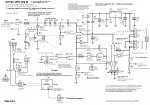
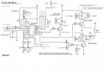
Here is the schematic!!!!

I have now attached the schematic for your observation.

But before you view it, I recommend that you please read the below to help you understand what it's supposed to do. I have tried to label everything as clearly as possible. The prototype has been built onto a PCB, so unfortunately, I may not be able to "test" all new modification suggestions straight away (PCB modifications or resorting to the 'breadboard' takes time!)

page1of2_JPG.jpgpage2of2_JPG.jpg

What the circuit does:
----------------------


This circuit is like a UPS (uninterruptable power supply) and provides a 5V and 12V output. The 5V supplies power to the Picaxe and any other IC's, whilst the 12V is the main power supply for an auxiliary 12V circuit that I will hook up to it - being an emergency lighting system (small, low current LED's), which I am also working on.

When AC mains power is available (via the 15V 2A adapter), devices connected to the Output are powered by this - actually, the voltage is dropped down to around 12.5 volts. When AC mains power shuts down (e.g. power blackout), a 12V SLA battery 'takes over' (switched via a relay; change-over smoothed by large caps) on the output line. I will most likely be using a 7.2Ah SLA.

I prefer the output voltage to be slightly higher than 12.0V... so around 12.5V to account for voltage drops. Otherwise I would have used a simple 12V regulator to drop the voltage down from 15V.

The battery is always connected to the charger, because it's a 4-stage charger that automatically drops the voltage down to 13.5V when the battery is full (charger's manual says it is ok to leave the battery connected indefinitely and no harm to the battery). Having said that, the Picaxe gives me the freedom to disconnect the charger (via a relay) at any time anyway. If the charger's power is switched off, the battery sits there in isolation (just about), but isolated from the charger completely to protect it.

The Picaxe monitors different areas of the circuit and provides visual and audible feedback (I will later be adding an optional serial 'LCD' output). It checks for things like voltage, temperature (mainly for battery charging), power state, 'output fuse blown' detection, and more. It also controls the battery charger and output via relays. If the Picaxe detects that the battery voltage is getting low, or critically low, it provides a warning and/or disconnects the Load.

Comments -
I understand some sections may leave some of you gurus shaking your head (sorry!) - like the first relay connected to the Input ('RL1')... but I had to somehow drop the voltage down as the relay's coil is 12V. This may very well be the problem with the resetting.... who knows.

One last thing... I will not be changing the 15V 2A adapter, so I am hoping we don’t change the Input section too much. Let’s keep it please?

I look forward to the hundred replies by the time I jump on again tomorrow, lol. Thanks guys! :)


When replying, please shorten the quotations! Cheers.
 

JimPerry

Senior Member
Seeing your partial schematic, and reading what you are trying to do, it seems that it may well be a code issue (not seen) - as the Picaxe is switching its own power supply about this may well be the problem - big caps are NOT enough. :confused:
 

hippy

Ex-Staff (retired)
There's a lot there and it's probably going to be difficult to say 'there's your problem' without further investigation, and that further investigation is going to be hampered by not having a scope. Without being able to see exactly what does happen we can only ever guess what might be happening.

First thing is to absolutely prove the PICAXE is resetting and that you are not seeing something else that just happens to look like a reset.

Then it's necessary to find exactly when it does reset, determine what the exact sequence of events will be leading up to that.

I'd probably start by putting the PICAXE on its own 3xAAA supply so whatever the rest does the PICAXE should be unaffected by that. That might give some pointers.

I would seriously suggest getting hold of a multi-channel DSO some way or other. Without that it's going to be hard to correlate this happens to that and then this.
 

srnet

Senior Member
as the Picaxe is switching its own power supply about this may well be the problem - big caps are NOT enough.
Yes, whats clear from the circuit diagram is that a relay is switching the supply to the PIC regulator from mains to battery. I would not be surprised if there was a PIC power supply line glitch in these circumstances.

As long as the mains supply is higher than the battery, then a diode in series with the two supplies, with both cathodes connected at the regulator should provide a relatively glitch free changeover. I have used this diode arrangement to switch a PICAXE between a 5v supply and an external 4.2v backup supply, it works just fine.
 

DirtBiker

New Member
I see R20 is 56ohms. Given a Vbe of about .7V that would mean a current of around 4.3/56=~77mA being drawn off pin 11 of the PICAXE when you turn on RL4. I am not sure that is causing your problem, but it is not advisable at any time.
 

premelec

Senior Member
I think you've got it DirtBiker ! assuming RL4 is the relay causing reset - worth a try increasing R20 to 200 ohms - though the Hfe of xistor may not be high enough to pull the relay [coil R not shown]. So many little details.... :)
 

boriz

Senior Member
Also, the 5v circuit is supplied through R4 and D3 and D4. If the 5v circuit draws about 100mA for example, from a 12v5 supply, as little as 4v could be driving your 5v regulator!

Also, throwing big capacitors into the mix isn't always a good idea. For example, they take a moment to charge, during which they draw a huge current. Easily enough to bring down your supply voltage long enough to cause problems.
 

boriz

Senior Member
The regulator datasheet says "Higher quiescent currents only exist when the regulator is in the dropout mode (VIN − VOUT ≤ 3V)." And the documented electrical characteristics are only for an input voltage of 6.25v and above.

So if the 5v circuit were to draw more than about 62mA the regulator would not be getting sufficient voltage to work properly.

Solution: Replace 68R with much smaller resistor, and, as was pointed out above, replace R20 with larger value, at least 220R. If there is subsequently insufficient collector current to drive your two parallel relay coils, then you'll need to re-design for a darlington or preferably a MOSFET.
 

jst3712

Member
The regulator datasheet says "Higher quiescent currents only exist when the regulator is in the dropout mode (VIN − VOUT ≤ 3V)." And the documented electrical characteristics are only for an input voltage of 6.25v and above.

So if the 5v circuit were to draw more than about 62mA the regulator would not be getting sufficient voltage to work properly.

Solution: Replace 68R with much smaller resistor, and, as was pointed out above, replace R20 with larger value, at least 220R. If there is subsequently insufficient collector current to drive your two parallel relay coils, then you'll need to re-design for a darlington or preferably a MOSFET.
Hi there,

R20: You're right... I forgot about the Picaxe pin current limitation. I was just thinking about the current needed to drive that particular transistor at the time. Oops. I will definitely look into this.

R4 (68R): I am not quite understanding how you came up with '4 volts' at the regulator's input via R4/D3/D4. I just physically tested the voltage and it came up with 8.6 volts on my multimeter with AC mains power removed, and I also removed RL1 relay from the socket to force power to flow from the battery via the these parts only - to test it. The battery's terminal voltage at the time was around 12.7 volts (no load). If I decrease the value of R4 as recommended, I am worried the regulator will steal too much power from the battery under Normal conditions (AC present).
 
Top