Minifig666
Senior Member
Hello again,
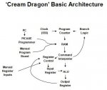
Today I am looking for a RAM chip for my upcoming TTL computer. It will be for program storage. I am looking for a chip that I can program with a PICAXE, probably a 18M.
I want to use a PICAXE to interface the RAM to save me the laborious task of hand programming.
I've been having trouble finding an 8-Bit wide serial RAM. The size is not too important, 64 lines would be the smallest I could do, 128 would be better.
I must admit that I aren't fully clued up on the topic and I'm lost as to whether an EEPROM would be better.
Thanks in advance, Minifig666")
Today I am looking for a RAM chip for my upcoming TTL computer. It will be for program storage. I am looking for a chip that I can program with a PICAXE, probably a 18M.
I want to use a PICAXE to interface the RAM to save me the laborious task of hand programming.
I've been having trouble finding an 8-Bit wide serial RAM. The size is not too important, 64 lines would be the smallest I could do, 128 would be better.
I must admit that I aren't fully clued up on the topic and I'm lost as to whether an EEPROM would be better.
Thanks in advance, Minifig666