Picaxe Pin use as In and Out ..

jackberg

New Member
Hello, I know the title lead to some questions but let me explain.

I currently use Picaxe 08M2, and I'm looking to interface a single pin to be use as input and output by the same internal program.

Maybe some of the users here had some experience with this, mostly in the electronic circuit.

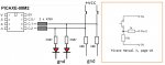
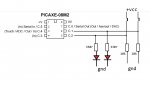
My goal is to interface a Led at Pinc.1 and Pinc.2 and also a switch for each pin.

My guess is if I'm using the "Dirs" command I can control the pin as "Output" for the Led, and "Input" when needed to read the switch status.

also to use a do,,loop to check the status of the pin before setting it as out, or In.

If this scenario make sense, let me know. (see diagram)

Thank to All.

25502
 

inglewoodpete

Senior Member
The circuit you are proposing should work. Rater that using the DIRS command, have a read-up on the "Input" and "Output" commands.
 

Flenser

Senior Member
Keep in mind that if someone presses a pushbutton while that pin happes to be set as an output with the LED turned off then you will have a short-circuit between 5V and ground on the pin which will probably burn it out.

I've never tried to do what you describe but a search came up with this page that has a circuit which doesn't suffer from this problem.
 
Last edited:

AllyCat

Senior Member
Hi,

Personally, I always use circuits like that "upside down", i.e. the LEDs from Vcc with their Cathodes to the PICaxe Pins, and switches between the PICaxe pins and Ground (whether I'm "sharing" the I/O function or not). There are numerous advantages; Firstly you can replace the 10k resistors with the PICaxe's internal "Weak Pullup" resistors, or (at least) Red LEDs will probably pull the input(s) high enough above the Digital Threshold to detect a button-press.

Another advantage is that the PICaxe's Output Driving "Pull-Down" FETs are much "stronger" than its "Pull-Up" FETs (i.e. a lower voltage drop for any appropriate pin current) so the LEDs may be brighter (for a given series resistor). Also in this application the Pull-Up current is probably not enough to destroy the pin Driver stage if you do accidentally activate the switch with the PICaxe pin in its OUTPUT mode. ;)

Cheers, Alan.
 

erco

Senior Member
Hmmm... are you making a Simon game with an 08M2? That thought has occurred to me, you need to multiplex the pins to drive 4 LEDs, read 4 switches, and play music. A clever old post by someone smarter than me shows how to use C.3 as an output (drive an LED via mosfet) by turning the built-in pullup resistors on & off.
 

hippy

Ex-Staff (retired)
I've never tried to do what you describe but a search came up with this page that has a circuit which doesn't suffer from this problem.
Something like that is what I would use; the 1N4148 appears redundant to me so I would leave that out. And, as said, internal pull-ups could be used to avoid having to use an external pull-up but, for the sake of one resistor, I'd go external to simplify the code.

The circuit could be simplified further if one were prepared to accept the LED being off while the button were pushed.

One thing to bear in mind is that any brief turning off of a LED will be much less noticeable than any brief turning on of a LED, so I would also favour an upside-down solution as suggested by AllyCat.
 

jackberg

New Member
And yes, as Hippy mention, the Led's turn "on" and "off", in sequence then the user press each switch in the same order to validate.
on error then a "fail" sound occur and the sequence re-start at the beginning.

Erco you are right about the "Simon Says" game a simple 2 buttons, 2 Led.

Also for the 4 buttons and 4 Led circuit I have to use a 12F683, and with PBP3 editor I'll look around this solution.

Thank's to all for your suggestions
 

hippy

Ex-Staff (retired)
Hippy, the author of that circuit gives this tip
blue and white LEDs have higher forward voltage drops than do many of the other colors. If you use a blue or white LED, you can avoid the need for the 1N4148 diode
It still seems redundant to me. I can't see there is any need to use a diode to create a voltage drop for a typical, red, green or yellow, LED. Just use a current-limiting resistor as one usually would.
 

AllyCat

Senior Member
Hi,

If you connect the LED(s) and switch on "opposing" rails, then the colour of the LED doesn't matter (except to possibly obviate the need for ANY separate pull-up resistor). Another advantage of the "Upside Down" configuration is that (unlike normal CMOS Logic inputs) the Digital Threshold voltage is significantly closer to 0v than to Vcc (there should be a much lower voltage across a closed switch than a LED !) and one side of all the switches can connect directly to a common Ground.

The main disadvantage is that the software needs to use "Active Low" logic, so that for example it needs a LOW LEDpin to illuminate a LED. However, for inputs you can use a SYMBOL Pressed = 0 and then IF BUTTONpin = Pressed THEN .... which is a good way to write "self-documenting" program code anyway.

Actually, the 08M2 has 4 complete I/O pins (including ADC inputs) as standard. You just need to remember that C.0 defaults to "Output" at boot-up/Reset, not to Input/Tristate like the other 3 pins. Then two more pins (C.3 and C.5) can be used as "Input Only" (C.5 needs a DISCONNECT command) and also as a "Weak Output" using the internal Weak Pullup resistors (C.5 may need a slight modification to the programming circuit and a POKESFR command). An advantage of the 08M2 is that ALL the pins are on a single port, internally called Port A (in the Microchip base PICaxe data sheet, for SFR commands) and named either Port B or C in PICaxe Basic. This means that it can support up to 6 Interrupt inputs (including Interrupt-on-Change flags) and 6 Weak Pullup Outputs. ;)

Pin C.2 is rather "congested" because it's the pin with the only PWM output, the I2C Data line (SDA) and (unofficially) a Comparator output, as well as having all the Normal Input, Output and ADC functions, etc.. Also, the 08M2 does have a few "missing" features (compared with other M2s) such as TABLE memory, Program "Slots", only 128 bytes of RAM and the RFIN/OUT commands, etc..

Cheers, Alan.
 

Flenser

Senior Member
I can't see there is any need to use a diode to create a voltage drop for a typical, red, green or yellow, LED. Just use a current-limiting resistor as one usually would.
Hippy, I didn't consider why when I posted the tip so I've gone back to check this and the diode is not in there as a part of controlling the voltage over, and current through, the LED,. It's there to ensure the voltage level meets the PIC spec for a logic 1 when the pin is an input and the button is not pressed.
- From the Wikipedia page LED Circuit "A red LED typically drops around 1.7 to 2.0 volts, but since both voltage drop and light frequency increase with band gap, a blue LED may drop around 3 to 3.3 volts."
- If I got the calcs right then when you use a red LED and no diode and the pin is an input and the button is not pressed then the voltage at the input pin will be about 0.1V above the voltage drop of the LED.
- From the PIC datasheet for the PIC12(L)F1840 chip (the 08M2). For 4.5V < VDD < 5.5V the Min Voltage for a logic 1 is 2.0V for a pin with a TTL buffer and 0.25VDD+0.8V for a Schmitt Trigger buffer (1.925V@4.5V and 2.175V@5.5V).
- My worst case calc with a red LED. VDD=4.5V - LED 1.7V = 2.8V across the two resistors. 2.8V across 26K is ~0.1 mA. 0.1mA through the 1k resistor is ~0.1V. Red LED 1.7V + ~0.1V across the 1k resistor is ~1.8V at the input pin.
- So if the red LED you happen to use has a low enough voltage drop then the circuit will not work without the diode but the circuit will always work without the diode if you use a blue LED.
 

hippy

Ex-Staff (retired)
So if the red LED you happen to use has a low enough voltage drop then the circuit will not work without the diode but the circuit will always work without the diode if you use a blue LED.
Thanks for the explanation. I can accept what it's saying but to me the solution would be to lower the 25K pull-up value or go for a different circuit configuration.

I am at a disadvantage of never having done it but I would have likely gone for something like this -
Code:
                          -.-
                    ___    |
---.   .-----------|___|---{
   |   |   | /|     ___    |
   |   }---|< |----|___|---'
IO |---{   | \|      _
   |   |    ___    _|_|_
   |   `---|___|---O   O---.
---'                      _|_
I would expect that top-most pull-up to not be required, but maybe is, though an internal pull-up could be used instead when reading the button.
 

AllyCat

Senior Member
Hi,
.... to me the solution would be to lower the 25K pull-up value or go for a different circuit configuration.
No and Yes ! :)

In the "original" configuration, the (switch) pull-up resistor actually feeds some current through the LED so it may well glow "dimly", at least indoors. I sometimes connect an "indicator" LED onto the "input only" pin (C.3 of the 08M2) and it's usually "bright enough" when driven by an internal Weak Pullup resistor, which is approximately 33k (25 - 200 uA in the Data Sheet). So lowering the 25k is not a very good idea, but changing the configuration (to an "opposing" arrangement as in #10 and #12) completely solves the problem.

The voltage drop across a Red LED might be 1.7 volts at its (full) operating current but it's much lower at the input switch pullup current of typically 100 uA ! It's difficult to find any data for currents below 1 mA, but below is an example. That's a typical, not a "worst case" graph (2v at 20 mA is quite high), but it's around 1.6 volts at 0.5 mA and perhaps halving for a 50 mV change, so the forward drop could easily be below 1.5 volts at 100 uA. Also, because of the human eye's logarithmic characteristic, typically a ten-times increase in current is recommended to "double" the subjective brightness. Thus the 100 uA might still appear as almost a quarter of the "full" brightness, so an even lower pull-up current might be desired.

RedLEDforwardV.png

The 1N4148 diode has a similar exponential characteristic, so its forward drop may well be below 500 mV at 100 uA (particularly at higher temperatures) so it's not even "guaranteed" to solve the threshold issue with a 2.0 volts input. Also, some PIC(axe) pins such as the 08M2's C.2 are NOT TTL but have "Schmitt" or CMOS input levels (the pin is intended for I2C/SPI input levels)! CMOS inputs are nominally 50% of Vdd (e.g. 2.5 volts); I doubt if the Schmitt levels are ever as high as 80% of Vdd, but they may well be significantly above 2.0 volts! :(

IMHO the best solution is to KISS as shown in Hippy's diagram, but probably the only "necessary" resistor is that in series with the LED. ;)

Cheers, Alan.
 

hippy

Ex-Staff (retired)
IMHO the best solution is to KISS as shown in Hippy's diagram, but probably the only "necessary" resistor is that in series with the LED
Without that the LED will light while the button is pushed, and one has to take care to never allow the IO pin to become an output high.
 

AllyCat

Senior Member
Hi,

Attempting to use a single pin for both Input and Output "at the same time" may require some compromises. Yes, if you specifically set the Output pin HIGH to hold the LED OFF, then pressing the button might not illuminate the LED. But of course at some time the pin needs to be polled (i.e. turned into an input) to detect if the button is pressed and then some current will flow through the LED. In principle, this need take less than a ms and then the drive can be restored, so the "blink" might not be noticed, but......

A resistor in series with the button typically needs to be lower than the resistor in series with the LED ! This is because the (worst case) Low threshold of the "TTL" input is 0.8 volt (at Vdd = 5v), so with 1.7 volts across the LED there could be 2.5 volts across the upper resistor. Thus the "button resistor" may need to be three times smaller, but to have made a Red LED "bright", the pull-up resistor might have been chosen around 150 ohms (i.e. 3 volts / 20 mA). Now 50 ohms directly across a "5 volt" HIGH output is hardly better than a short-circuit, although 100 mA is NOT going to flow, because of the output resistance of the PIC(axe)'s pullup FET. But the Output Pin may be pulled low enough to allow the LED to glow anyway when the button is pressed, and/or the 25 mA current rating of the pin might be exceeded.

Therefore, I (still) take the view that the button series resistor is not strictly "necessary" and that it's simpler (and safer) to switch the Output pin between LOW (to switch the LED ON) and INPUT ("Tri-State") to switch the LED OFF. Certainly the LED may blink when the button is pressed, but this could be minimised by rapid polling.

Theoretically, IF the program-writer accidentally sets the Output pin HIGH and the button is pressed, then the Absolute Maximum pin current might be (slightly) exceeded: Figure 31-41 (page 360) of the Microchip 08M2 PICaxe base data sheet shows that at 5.5 volts, a "Typical" Short-Circuit current of around 35 mA at 25 degrees C may flow. This is far less than the pull-down S/C current, which could be 80 mA (Figure 31-42), that might damage the chip. There is no data specifically for 5 volts, but Figure 31-43 at 3 volts shows a very "safe" S/C current of 11 mA and the pull-down just on the 25 mA limit. Taking an average suggests that a typical PICaxe Vdd = 4.5 volts should be within the Absolute Max (Pull Up) current and it's very unlikely that damage would occur at 5 volts, particularly as these currents fall back when the temperature rises above 25 degrees C. ;)

Cheers, Alan.
 

jackberg

New Member
Hello,

An inline resistor for each Out could be use as a load de-coupler between the +VCC and output Port.
Also I set the DIRS for 1 second as output just before sending a high to the Led, and back to input when waiting for a switch.
I did setup this circuit and it's seem to work fine so far, even while holding the switch to +5vdc.

"Really appreciate all the feedbacks"

"Still Learning"

25506
 

inglewoodpete

Senior Member
Hello,

An inline resistor for each Out could be use as a load de-coupler between the +VCC and output Port.
Also I set the DIRS for 1 second as output just before sending a high to the Led, and back to input when waiting for a switch.
I did setup this circuit and it's seem to work fine so far, even while holding the switch to +5vdc.

"Really appreciate all the feedbacks"

"Still Learning"

View attachment 25506
Yes, that's a good overall solution.
 

AllyCat

Senior Member
Hi,

Certainly it's completely "safe", but a little "strange" that the LED will be somewhat brighter when the button is pressed, compared with when the PICaxe drives it. And there's nothing that the PICaxe can do to prevent this illumination all the time the button is pressed. :(

Assuming the LED has a 1.7 volts forward drop, then when a button is pressed there's 5.0 - 1.7 = 3.3 volts across the 330 ohm resistor, giving a convenient 10 mA current through the LED (and another 0.5 mA flows in the 10k resistor).

When the PICaxe drives the LED, the series resistance is 330 + 470 = 800 ohms, so approximately 3.3v / 800 = 4.1 mA will flow. But at around 4 mA, the PICaxe output FET drops about 0.4 volt, so the current through the 470 resistor will be nearer to (3.3 - 0.4) / 800 = 3.6 mA, and the resistor will drop around 3.6 * 470 = 1.7 volts. Thus 5.0 - 0.4 - 1.7 = 2.9 volts is applied across the 10k resistor, or 0.29 mA through this resistor and 3.6 - 0.29 = 3.3 mA through the 330 ohm resistor and the LED. Therefore the PICaxe can drive the LED at only one third of the "button pressed" current !

Cheers, Alan.
 
Last edited:
Top