PICAXE module boards, tell me what you think.

harolds1956

New Member
Here are a few picaxe boards I made up test out programs or embed into a new project. The 20 pin modules will accept the 8m,14m, or 20m chips. Pin outputs use either male/female headers or terminal blocks. Pictures aren't the best as I used the only camera I had from an old Iphone. Let me know what you think and any comments or improvements/modifications you have.
 

harolds1956

New Member
I know, tried several times to upload without success. The pics are jpegs. Tried using the "attach files" and "insert image" tags. Perhaps someone could guide me on what I am doing wrong?
 

harolds1956

New Member
Thanks for the link. I read and have not changed my email address. Went thru my "profile" and other parameters and see nothing more I can do with my account. I assume that if I wasn't "activated" I could not see others attachments (I can) or even post. Maybe the forum could "re-activate" my account?
 

Jack Burns

New Member
I suspect the picture file sizes are too large.
According to the help page, you may attach up to 5 images, max size 1024k each. Supported types are jpg and png.
https://picaxeforum.co.uk/help/images/

If the file sizes are okay, then check how the picture files are named... filename.jpeg OR filename.jpg?
If they have the .jpeg extension, then try renaming them to a .jpg extension and see if that works.
 

Technoman

Senior Member
.jpeg or .jpg is an extension that may be given to the same file. Some old versions of Windows were only accepting 3 letters extension, not anymore.
 

Technoman

Senior Member
Good job although the idea of a Picaxe stick is not new, some even including an USB interface, with pins underneath, to be inserted into a breadboard or a socket.
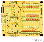
Power supply via a DC power jack : you'll need a 3 to 5V maximum power supply as you don't have an on board regulator as, e.g., theAXE401 board.
Power supply via an micro USB port : have you any device (fuse, ...) to protect the power supply (if not) or the computer?

If I had to design a new board which would be seldomly reprogrammed, for the downloading circuit, I would choose the 3 pins solution (JST) as documented in Picaxe manual 1 (pages 27-28) : smaller, easier to fit, cheaper. Still, a special cable DB9-3 pins female JST connector has to be made.
And ,may be, a JST 2 pins connector for the power supply...
 

kfjl

Member
Your boards only seem to have one GND connection. What do you do if you want to connect several modules that all need a common ground with the picaxe?
 

marks

Senior Member
hi harolds1956,
I just finished making a new project board
easy to plug in a 8m2 14m2 20m2 20x2
at the moment only power is conected to the top two socket pins
the required serin pulldown 15k is on the optoboard
if i need to test a 18m2 i can just drop down a slot
and carefully connect to the correct pins
 

Attachments

thunderace7

New Member
When I was teaching myself to use Fritzing I designed some boards for Picaxe projects. Ive never had any made into actual boards yet but I probably will sometime.
The board for the 20 pin Picaxe incorporates options for either the 3.5mm jack or the 3 pin header for the programming socket. It is not wired as shown in the manual but I have made a small adaptor for use with the standard AXE27 cable.
 

Attachments

harolds1956

New Member
Some of the boards have the micro USB jack and others have the female barrel jack. I have a bunch of USB to micro USB/barrel jack adaptors so that's what I used. (Also have many USB output "wall warts")
Except for the smallest 8m board and the one with the terminal blocks I have at least 2 additional grounds (and V+ outputs) so I can power sensors etc. without having a separate power supply. Most of the boards have 3 additional grounds and V+ outputs. They are hard to see but are male/female headers (not labeled!) that are extended beyond the chip outputs. Some boards have the additional headers placed at the board ends.
Should be noted that most of the boards have no mounting holes. Did this for 2 reasons: I can reduce the board footprint, and can mount the boards using silicone rubber.
 

Attachments

comet

New Member
Great! I‘m using a lot of Microcontrollers, but I always back to the Picaxe, if I want to do ist fast. I had written an Introduction to PICAXE in 2013 or so at the German Site Elektronik Labor by „Kainka“. I have to learn that there was an Special at German „Make:“, Maker Magazin of Heise.de. The complete Article with a Picaxe Board for 08, 14 and 20 and a 08M2 costs about 25€. A Picaxe 08M2 is included. The Board can be buyed extra for around 9€ (includes 08). A USB Connector is on Board.
Best regards Juergen
 

Tvmender

Active member
Hi

I quite often attach my project board to a small piece of MDF and take fly leads to screw down terminal block which has made prototyping much easier.

In my lasertag project I actually made a header for a board such as RKP28C to fit directly onto the main board as a riser. This allowed the PICAXE to retain its ISP features etc. and freed up a ton of board space below.
 

saunj

Senior Member
I have attached an assembly to a solderless breadboard for Picaze tests.. It has a coax jack for 7-18 v power, a switch and 5V regulator, a DC-9 socket for programming and protection circuit and a test switch. There are also 3 leds with ballast resistors. The wires from this go to the end of the breadboard for convenient jumping to any size Picaxe.
 

geezer88

Senior Member
For some simple projects, I solder all the components to each other, then, when it works the way I want, I squirt hot melt glue all over to seal it from the environment. Looks like crap, but outdoor stuff seems to hold up just fine.

tom
 

papaof2

Senior Member
My philosophy about the appearance of things that survive the weather? If it keeps working, it's beautiful!
 

gertvdwalt

New Member
I designed this board for a friend of mine that has has whole lot of Arduino based robots that he had made and now his new boss wants him to use PICAXE instead. So as not to waste these robots this board will replace the Arduino with a 20M2 with an onboard CH340 serial chip. I told him about the AXE401 that already exits but the requirement was that they must use the 20M2 and since there is no need for a power supply etc (power comes directly from the robot) this seems to be the best solution.

I want to upgrade it to have the option to have a power supply should it be needed, since it will only require me to put traces and maybe a couple of jumpers on the board, but that will be for the future.
 

Attachments

Top