PICAXE keeps failing

Andrei IRL

Senior Member
Hi everyone.
I have a strange failure of the PICAXE M08 chips and i can not figure it out.
The worst part about it after the chip has failed it send one of the PINS high which turns on a relay killing everything connected to it.
Is it possible to have a Fail Safe to prevent that?
I have used same curcuit for many years and it worked perfect, the only difference this time is the use of PNP proximity sensor.
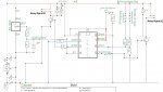
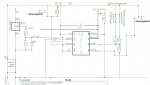
PNP Proximity sensor sends out 12V signal which is brought down to 3.8V by the use of Voltage devider and as a precaution i also have a 4.7v Zener.
So the only thing i could think off is that Proximity sensor kills the chip.
I have tested this curcuit over many of hours running off a 12V battery and it works perfect. However, this project is for a motorcycle.
Ignore the power supply in the diagram as im using LM7805 with Two caps at either sise plus 100nF right at the Chip.
Im thinking may be i would be better off with a NPN Proximity sensor then i'll be reading LOW signal as my trigger and no fear of excessive voltage killing the Chip.
I would appreciate any ideas ye might have.
P.S. I did check all the signals with a scope to make sure the proximity sensor is not creating any back EMF and it all looks good (bench tested only not while on a motorcycle)..
Thanks very much.
Schematics Andrei.JPG
 

The bear

Senior Member
Hi Andrei,
Nicely drawn circuit.
Doesn't seem to be a problem with your sensor.
How is the relay killing everything?

Regards, Bear..
 

premelec

Senior Member
Are your relays driven by transistors? In short what's the circuit that relays 1 & 2 go to... maybe you've just been lucky in past or changed relays... anyhow more circuitry would be appreciated to solve problem...
 

Technical

Technical Support
Staff member
So when the relay contacts are open the two PICAXE inputs are floating and could therefore float either high or low?
 

Andrei IRL

Senior Member
The ignition is running through a relay. Im basically disrupting ignition circuit when proximity sensor is activated. It is not good that the cip fails and even worse that relay controlling pin goes HIGH.
Diagram does not show but im running a BC337 Transistor on the relay signal pins.
I had the whole thing hooked up to a test jig for hours on end and it was fine. The test jig was just a fan spinning with two screws in its fins which were triggering the sensor.
I was feeding the while circuit with 24 volts just to make sure to give it a good stress test (before the voltage regulator, proximity sensor working voltages are 10-30V so directly connected to the power source).
I re drew the exact circuit im using bellow.
Thank you.
Circuit with Transystors and Two step and Zener.JPG
 

Andrei IRL

Senior Member
Sorry i dont follow, probably mushy brain haha.
I only have one sungle input the the PICAXE that is activated via Proximity sensor.
All inputs are grounded via pull down resistor so that should not be an issue.
Relays are controlling something completely outside this circuit.
Not 100% if i answered everything here.
Ive been going around in circles and its driving me crazy.
Is it possible to get a bad batch of Chips ta all?
 

Andrei IRL

Senior Member
Are your relays driven by transistors? In short what's the circuit that relays 1 & 2 go to... maybe you've just been lucky in past or changed relays... anyhow more circuitry would be appreciated to solve problem...
Thank you, i have added full circuit above.
 

Andrei IRL

Senior Member
The code changed to accommodate couple of new function but in theory the main code is same as before. I have a bit of new code which is only executed on the start up and if nothing is pressed then the code just goes to the main part which is ran over and over and over... Is looking for a high input from the proximity sensor and then triggers the relay. That's it. Super simple.
 

inglewoodpete

Senior Member
PICAXE chips are pretty tough, provided you use them within their limits. In my experience, it is extremely unlikely (like a million to one!) that you have bought some duds. Either they are actually working fine or you have damaged them with excessive voltage, reverse voltage or drawing excessive current.

Relays are controlling something completely outside this circuit.
That means there is no wiring connection, even a 0v link, between the control circuit and the switched circuit?

I don't understand your power supply drawing for the PICAXE. It's drawn with 5v appearing on the input of the LM7805. Do you have the right component wired the right way around?
 

Andrei IRL

Senior Member
I'm sorry, your are right, I have placed the lm7805 incorrectly on the diagram. But I can assure you is connected the right way within the actual circuit. The controlled circuit and the picaxe circuit share a common ground.
 

neiltechspec

Senior Member
The fact that it bench tested ok & fails on the bike is the clue.

A bike like a car is a very hostile environment for electronics.

I have done quite a bit of car PICAXE projects, for some of them I experienced various random resets.
I ended using screened cable on all external cabling, transient suppression on the input to the voltage regs,
transient suppression on all input signals & back emf suppression on all relays.

Neil.
 

rossko57

Senior Member
It was said earlier "Im basically disrupting ignition circuit ", I think that could be re-phrased as "I am commanding the transient generator to make a bigger transient". I'd follow Neil's advice, noting screened cable particularly for your pickup.
 

techElder

Well-known member
Although Andrei hasn't specifically stated this, I am assuming from his comments previous that this is some sort of theft deterrent system.

In that case there won't be any "transients." The engine won't be running; especially if he gets this device working.
 

Andrei IRL

Senior Member
Thank you for all the replies.
Just to clarify a few things:
The bike will be running, this system not part of an alarm (i wish it was, may be next project).
I have one other PICAXE circuit (shift light) running on the bike for a few years with no issue.
I have used exactly same LM7805 voltage regulator circuit for all picaxe's currently on the bike.
From what i can tell, the only new component i have in this circuit that i have never used before is the proximity sensor.
What i have done today was:
Replace all wires with screened cable and also added an additional voltage regulator (LM7812 and a couple of caps) before the LM7805.
This way, the proximity sensor is always getting definitely no more no less then 12V stable voltage. Up until now i was relying on the voltage regulated by the bikes voltage regulator only.
Thanks very much for all the help once more.
Im super delighted to be a part of this forum.
 

BeanieBots

Moderator
It worked fine on the bench is a very common quote!
Unfortunately, real life applications are very different to a 'bench' environment, especially automotive. You can expect to see extreme voltages. In excess of 150v spikes on the 12v line is not unheard of. That is why a 7805 regulator should NEVER be used in an automotive environment.
This is also why people are very reluctant to give advice on any circuits that are to be used in an automotive environment. Failure can cause other parts of the original automotive circuits to fail which can result in disaster.
Please have a read of this article:-

http://www.google.co.uk/url?sa=t&rct=j&q=http://www.industrologic.com&source=web&cd=3&ved=0CC0QFjAC&url=http://www.industrologic.com/autotransients.pdf&ei=VRlJUMTFEIeo0AX7tYCABA&usg=AFQjCNFu4bnQm0t4L4AuHIAxs5k59lgO0g

Does your circuit ever fail when used 'on the bench'?
 

tmfkam

Senior Member
I was going to make the points that NeilTechSpec made. But he's done that already.

I recently made a device to control three large-ish (48V) motors using relays to power the motors on and off and to reverse the motor direction, with PWM of the 48V supply to control the motor speed. This worked well in initial testing which for simplicity used only 24V for the motors. Once connected up at the full 48V, I was getting random resets. I checked that I was setting the PWM to zero before activating/deactivating the relays but struggled to pin down the cause of the resets. I found that this only happened when one of the limit switches for one of the three motors was in the open circuit state, if I held it closed, no resets occurred. This surprised me as the switch inputs to the PicAxe are pulled high by 470R resistors. Still, feeding the input from the 'rogue' limit switch through a BC547 (and inverting the switch logic in the program) has cured the problem totally. I can only assume that the back EMF from the motor PWM was inducing a voltage spike in the wiring loom before finding it's way back to the PicAxe.

It might be worth considering connecting all 'off board' inputs and outputs (such as those for the relays, proximity sensor and switches if they too are remote) to Opto-Couplers before connecting the inputs and outputs to the PicAxe which may help remove any spikes which may be picked up on the wiring. If the inputs and outputs could be connected to the Opto-Couplers in such a way that they do not share any common earths that too might help reduce unwanted interference.

Good luck.
 
Top