Picaxe Experimenter Board Axe090 Voltage regulator bug?

galmiche

New Member
Dear All,

I have mounted the AXE 090 Board.

BUG: The voltages ooff my battery is 9V or so. The Voltage on the chips + pins, stay around 8.5 , far away from the admitted 5V.

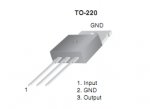
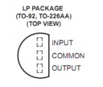
My 7805CT voltage regulator is soldered as on pictures, metallic part against the board, viewing name on top.
Placed as I can read the regulator name, pins bottom: If I well look , the POWER+ input connector is connected on the right pin of the 7805 marked DC; the middle one is to ground and the left one (marked +) goes to chips.

I think this voltage regulator is wrongly cabled. Pins 1 and 3 (left/right) should be inverted as the voltage may in on the left pins and out on the right one.

Can you please confirm that the 7805 has to be flipped top/bottom to reverse it?

Thx for help,
Sincerelly.
Hervé
 

BCJKiwi

Senior Member
If it is a 7805 which is in a TO-220 package then it would appear to be back to front.
If it is a 78L05 in a T0-92 package it is still the wrong way around.

The data sheet for the actual device you have will give you the correct info.
Be sure the device is oriented the same way as the datasheet diagram. Sometimes they are specified looking from the bottom, sometimes from the top!

These are National and Fairchild diagrams.

Is it possible that the cable to the DC input connector has Plus V & 0V reversed?

Also note the power supply details as follows (from the AXE 090 manual);
"Power Supply:
There are two options on how to provide power to the Experimenter board, but
ensure only one option is connected at any one time. The PWR LED indicates
power to the board.
1. Battery - connect a 4.5V (3xAA cell, not supplied) battery box to the screw
terminals, ensuring correct polarity. Do not use 6 or 9V battery packs.
2. Power supply - connect a regulated 9V DC power supply with 2.1mm
(positive tip) connector (not supplied e.g. part PWR009).
The power supply connection is regulated to 5V by the 7805 regulator
and reverse polarity protected by a diode.
The screw terminal battery connection is not regulated and so connects
directly to the PICAXE chip. Do not use a 9V PP3 battery on this
connection. Only use a 4.5V (not 6V) battery pack."
 

Attachments

Last edited:

galmiche

New Member
Solved

"The screw terminal battery connection is not regulated and so connects
directly to the PICAXE chip. Do not use a 9V PP3 battery on this
connection. Only use a 4.5V (not 6V) battery pack."


That was my mis-done. I used a 9V battery to the screw. :( I HAVE to use 4.5V to screw entry points

Thx for Help.
Solved.
 

muckypups

Member
Hi,
I accidentally put 9v through an 18X the other day, and it survived. It was only a brief contact, maybe 2 seconds, but it seems to be ok. I have reprogrammed it several times since, and it seems none the worse. Lifespan may have been affected though. The Xbee that was connected to the same bus didn't survive unfortunately :(
One interesting consequence was that before the blowout, the picaxe had to be running at 8x to transmit intelligible serout to the xbee, but since I swapped out the xbee, I have to run the axe at 4x. This could be due to a different xbee chip but the only difference spec wise is the new one has the chip antenna, versus the old ones soldered wire. Both series 1 chips.
Odd anyway.

alan
 
Top