Picaxe based Volt/Amp Meter

Mad Professor

Senior Member
Good Day All.

I would like your thoughts and suggestions before I start my next project.

I will try and explain the basics of what I want to do.

My old man is very into green engey find solar and wind.

He now wants to be able to monitor in close to real time the voltage and current each solar panel and wind gen is making.

I have to get the real time data from the slave device(s) connected to the output of the solar panel or wind gen, to a PC to show live data and log the data.

I have two ways of doing this, (1) via wires or (2) via wireless connection.

I would like to go down the wireless route, but this is something I have no worked with yet.

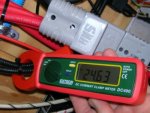
The monitoring units will have to read 0-24vdc and up to 10amps.

To start with I am only looking at making one slave (monitoring unit), and what ever else is going to be needed to get the data into a PC.

But if all go’s well I would be looking at expanding up to 8 slave units.

So I know I am going to need a PicAxe with at least two ADC ports, and as I am going to be using the ADC ports I am going to need a super stable voltage to the PicAxe chip.

So I would now like you thoughts and suggestions.

Thanks for your time.

Best Regards.
 
Last edited:

Dippy

Moderator
Break it down.
Measure and send. Dead simple.
There are dozens of very good current sensing chips available. Let them do the hard work.
Measuring voltage will be a pot-div into your ADC.
Radio modules range in difficultly, depending on how much you want to spend.
But, in principle, they are dead easy and there are zillions on the market.
DON'T be tempted to buy the cheapest unless you have a short range and no noisy neighbours.

Post a picture of your proposed schematic.
And tell us your (Dad's) budget.
Should be a piece of cake - unless you expect to do it for under a tenner.
 

Mad Professor

Senior Member
Dippy: Thanks for you quick reply as always.

As for the budget thats not set in stone yet, as we have to work out how much it's going to cost as we would like to go down the wireless route.

The range of the radio would need to be around 20-25m.

But as I have not worked with radio before that is way I have asked what would you suggest.

eclectic: Thanks for the link, I have done a search on the forum and have been reading alot of the post, to try and come up with some ideas.

The units will be taking there power from the batterys that are being charged from the wind gen and solar pannels, the bank of batterys are 1100amps yes thats right, so are not going to go flat quickly, but I still need to that the battery / charging power down to a stable 5volts for the picaxe.
 
Last edited:

Andrew Cowan

Senior Member
What voltage are the batteries?

I'd either use a 7805 regulator (plus caps) or a DC-DC convertor to power the PICAXE and radio (if 5v).

A
 

Mad Professor

Senior Member
Andrew Cowan: It's a bank of ten 1.2volt 1100amp batteries, so 12volts wile not being charged, but wile being charged can see anything up to 15volts.

I would be looking at using a suitable 5volt regulator + caps for powering the Picaxe.
 

BeanieBots

Moderator
A good quality regulator should be fine as your voltage reference. The trick is not to load it with anything that switches highish currents. If you need anything that does want current at 5v then use a seperate regulator for it and make sure the return current path is not shared with the PICAXE.

As has been mentioned, a potential divider will be the easiest way to monitor voltage but make sure it thevenin equivalent resistance (R1*R2)/(R1+R2) is less than 10k and use the enhanced download circuit.

With a bttery that size, I'm assuming you will also have an inverter near by?
These are VERY noisy. Use seperate leads for it and keep them well clear of your analogue circuitry. Also, make sure your 5v supply is well decoupled with 100uF, 10uF and 100nF. (don't forget the regulator caps).

10A is bit high to get get much voltage from a sense resistor so you will need fairly high gain if you take that path. High gain plus a little noise = a lot of noise so take great care with layout and again, good decoupling.

For the voltage, you might not care about anything below around 10v. In which case you might consider using a differential amplifier to increase the resolution of the range of interest.

Do you want EVERY reading sent back to the PC?
Maybe do some local averaging/summing and only send the results.

On mine, I process locally and only store the peak & average for each day.
Every week or so I then transfer (via a cable) to my PC.
 

Dippy

Moderator
For current sensing, take your pick.
http://uk.farnell.com/jsp/search/browse.jsp?N=500006+1004547&Ntk=gensearch_001&Ntt=current+sensor&Ntx=mode+matchallpartial

A BB says, it is crucial with any ADCing that the Voltage supply to your PICAXE is smooth and stable.
In a Solar Charger design i did a while back there was a lot of switched mode noise kicking about, so I made a little sub-board with PIC+Current Sensor - thus the main PIC interrogated it digitally. A bit like a DSB digital sensor. Maybe you can get digital current sensors now, I can't be arsed to look .

What YOU need to do is plan it out like a schematic and make sort of shoppng list of parts.
This is the sort of subject that gets everyone interest, so if you post a plan and a picture then you'll just have to sit back.... and the answers will appear like magic ;)
 

Andrew Cowan

Senior Member
Andrew Cowan: It's a bank of ten 1.2volt 1100amp batteries...
Do you mean 1100mAh?

10A is bit high to get get much voltage from a sense resistor so you will need fairly high gain if you take that path. High gain plus a little noise = a lot of noise so take great care with layout and again, good decoupling.
My robot has a 0.0015 ohm sense resistor - coupled to an op-amp, it provides a great current sensing feature. I have plenty of smoothing, so very little noise. The op-amp has a gain of 100.

A
 

manuka

Senior Member
More details on your dada's greenie devices needed! Is he just making a 100W hacked Smart Drive wind gene or rivalling the likes of Vestas MW offerings? Backyard wind farms initially often involve numerous mechanical problems, & electrical issues may be secondary. What sort of wind resource do you have at that IoW site? Any NIMBY neighbours? If still considering PVs, check CIGS [Copper Indium Gallium (di)Selenide] types that are superior in "less than ideal" solar environments-colonial tease re. Blighty weather!

I've - modest cough - a fair bit of hands on experience in this field, & echo BB's views that too much data may overwhelm, especially if just "proof of concept" is being explored. Given the 20-25m distances I suggest you forget wireless & just link directly as well.

Cheap PC connected data logging multimeters are often the most feasible initial technique anyway, & I've long used the likes of the US$40 Jaycar serial QM-1538 to great effect, but "EM6000" types now abound. See Maplin's £40 USB offering ! that comes c/w serial-USB cable (possibly suiting normal PICAXE use too!?). Such datalogging DMMs readily log almost anything electrical, & the marvellous PC displays are a goldmine when tweaking. As it's often the daily wind/solar "sky mining" Amp.Hour gain that's of greatest interest, even consider a simple PICAXEd bike computer hack.

IMHO, & as most off grid setups have heavy duty wiring & cussed connections, one of the handiest monitoring devices can be a AC/DC clamp ammeter. The AC form of course has long been a sparky essential, but the (Hall Effect) DC types are now a near indispensible non invasive electrical tool (auto electrical work especially).

Stan. - sunny NZ.
 

Attachments

Last edited:

papaof2

Senior Member
The easiest-to-use current sensors are probably the AmpLoc devices, where you simply run the current-carrying wire through the device. The US site (pictures and small quantity purchases) is here http://amploc.com/store/index.html The AMP25 and ZAP25 (25 amps) devices are $12US plus shipping.

Datasheet is here http://www.amploc.com/AMP SERIES 25-300.pdf

Note that the devices are linear at some level of overcurrent (60A for 25A units, 95A for 50A units).

John
 
Last edited:

manuka

Senior Member
Thanks for the heads up- these Amploc Hall Effect DC sensors look very PICAXEable. However don't forget they need prewiring, & can't be opened up to straddle a wire already in place!
 

eclectic

Moderator
Current thread

"Current: try post #12 here:
http://www.picaxeforum.co.uk/showthr...current&page=2"
e
 
Last edited:

papaof2

Senior Member
Thanks for the heads up- these Amploc Hall Effect DC sensors look very PICAXEable. However don't forget they need prewiring, & can't be opened up to straddle a wire already in place!
True. But since there were "add a sense resistor" posts (which also require opening a connection), the AmpLoc provides a calibrated readout for the same amount of work. An alternative method might be to add a new wire threaded through an AmpLoc, then remove the original wire - works for things brought out to terminal strips, but not so well for soldered connections...

There are also clamp-on DC current monitors, but most are probably out of reach ($$$) for hobby use :-(

John
 

manuka

Senior Member
The Jaycar Digitech QM1564 DC clamp meter I swear by cost ~US$60 & is similar to this . It's not much use with currents below 100mA (!), but otherwise has been a real winner, especially accessing tight mains wiring that my normal AC clamp is too bulky with.
 
Last edited:

Taniwha

Senior Member
1100ah Batteries

Andrew Cowan: It's a bank of ten 1.2volt 1100amp batteries, so 12volts wile not being charged, but wile being charged can see anything up to 15volts.

I would be looking at using a suitable 5volt regulator + caps for powering the Picaxe.
these sound like nicads? I sell GEL and AGM batteries up to 3000ah (yes that is amp hour) but the sealed lead acid cells are 2 volt nominal so 6 of them give 13.8volts float.

Stewart
 

Mad Professor

Senior Member
Regarding the batteries I have just spoken to my old man, and I was worng with the details I said.

The batteries are infact 2volt each and around 1100amp, the batteries are 200x200x550mm, and are lead acid type, There are no labels on the batteries so I have been unable to find any details out regarding them.

I have been looking on RS for current transducers, what do you think of thease two 666-8185 and 667-3455, The 1st one only needs a 5v ref, where the 2nd one needs 12-15v ref.

Yes we do have an invertor connected to thease batterys, the invertor is a ProSine 1000i

To try and keep things more simple I think I will not go down the wireless route quite yet.
 
Last edited:

papaof2

Senior Member
Note that the second device is a "current loop" device whose output *current* (not voltage) changes with changes in the current of the circuit being monitored. Also the power for the device is +/-12volts to +/-15volts, so you need a split power supply (+12 above common and -12 below common) to operate it.

John
 
Top