Hi,
Yes it would generally be better to "scale" the potential divider to match the reduction in supply voltage. I must admit that I was more considering the situation when the PICaxe is put to (indefinite) sleep rather than having its power supply totally removed (if it is
*). But there should be a decoupling capacitor directly across the PIcaxe supply rails, so it's worth considering what might happen (or not happen) if the button is pressed shortly after the PNP switches off (but the reservoir capacitor has not yet fully discharged).
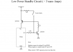
1.5 volts should be ok on the base of the npn transistor?
The base voltage never actually
reaches 1.5 volts, because the base-emitter junction is a forward diode. If the potential divider tries to pull up higher than about 600 mV, then current flows into the base and is amplified by the transistor (which is its primary purpose, of course). So the base voltage will (should) never rise above about 700 mV.
* FWIW, I would rather dispute the "3 nA standby" claim. Is the "open circuit" resistance of the touch switch (and leakage current across any PCB tracks) really greater than 1G ohms (1,000,000,000 ohms) ? Also, the data sheet for the "2N3904/6 doesn't really give sufficient detail, but the collector-base leakage (Icex) is specified as "up to 50 nA" (personally I prefer Iceo in specifications). The specified leakage is at the maximum rated voltage, but at only 25 degrees C; we can only guess what it might be at 3 or 5 volts, but with elevated temperature. However, the leakage current can then be amplified by the NPN transistor (and then by the PNP), so the current fed into the PICaxe might be
much higher.. To work well in "adverse" conditions one would normally add high-valued resistors (say 100k +) across most base-emitter junctions (to prevent any leakage currents being amplified by the transistors).
Cheers, Alan.