Okay, so I understand the reasoning behind using 3 "aa" cells and have made a dummy cell as I can only get a 2 "aa" case or a 4 "aa". My question is, what if you need to power motors, lcd displys or keyboards and the like. What do you suggest there and what would be the best way to isolate the power to the motors from the picaxe to stop noise etc when using the L293 motor driver i.c.? How do you run two supplies? Just tie the grounds together?
Picaxe and addon power sources
- Thread starter nzdragme
- Start date
inglewoodpete
Senior Member
You should be able to get a switched 3-cell battery case at Dick Smith Electronics. I know there is one in Chch because I've been into the shop.
Connecting the ground is the minimum and will usually suffice when using two supplies.
ylp88
DSE still sells electronics things? My local stores are phasing out everything! The one I used to usually go to doesn't sell any components (except for automotive fuses) or plugs and sockets!You should be able to get a switched 3-cell battery case at Dick Smith Electronics. I know there is one in Chch because I've been into the shop.
ylp88
Lots of options and no right or wrong answers. My personal preferences:
* Quick and simple "flash a led" demo = 3 batteries.
* Ditto any "educational" demostration = 3 batteries.
* Running a motor = 3 batteries for the picaxe, and 3 or 4 for the motor and join the grounds together.
* Running an LCD and/or other digital chips = low current 5V = maybe a 9V and 78L05
* Any sort of analog sensing = 9V batt and 78L05
* Permanent installation = run off a 9-12V plugpack and use a 5V regulator.
* Permanent installation not near mains = 12V SLA, solar panel, solar charge reg and low quiescent 5V reg.
hippy
Ex-Staff (retired)
On isolating power, two separate supplies are best for that and just the 0V ( "grounds" ) need to be connected together. That does require that the motor drivers can work this way, that voltage for the motors only goes to the motor. I believe the L293D works that way so no problem.
For LCD's, keyboards and the like it's common to run them all from the same supply as the PICAXE but to add decoupling capacitors to reduce noise introduced onto the power rails. A 100nF next to every chip and connector across its +V and 0V is the rule of thumb.
It is possible to run everything off its own separate supply with just the 0V's connected but more care needs to be taken that the voltages to each don't cause problems with other parts of the circuit. Running something at 5V and a PICAXE at 2V is likely to damage the PICAXE unless precuations are taken to prevent that. Such precautions usually involve current limiting resistors or voltage level-shifters.
Another alternative is to take the raw input supply ( say 9V or 12V ) and run that through same voltage regulators, each of which supplies a separate part of the circuit. As this is more costly and has its own potential problems it's usually only done when there is a particular issue to solve or a single regulator cannot handle the current demand of the entire circuit.
Mycroft2152
Senior Member
Dr.A,Lots of options and no right or wrong answers. My personal preferences:
* Quick and simple "flash a led" demo = 3 batteries.
* Ditto any "educational" demostration = 3 batteries.
* Running a motor = 3 batteries for the picaxe, and 3 or 4 for the motor and join the grounds together.
* Running an LCD and/or other digital chips = low current 5V = maybe a 9V and 78L05
* Any sort of analog sensing = 9V batt and 78L05
* Permanent installation = run off a 9-12V plugpack and use a 5V regulator.
* Permanent installation not near mains = 12V SLA, solar panel, solar charge reg and low quiescent 5V reg.
That's an excellent summary, but I would make one slight correction. I would change4 tio 78L05 to any low dropout, low quiescent current regualtor.
The 78L05 is very old technolgogy and seems to be imprinted in our minds. Unfortuantely compared to current technolgoy, the 78L05 is quite a current hog at 3 ma versus micro amps. the newer te4chnology provides extended battery life and a greater operating range during battery life.
Myc
Last edited:
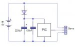
You can run something very noisy and a PIC off the same power supply by adding a diode and large capacitor before the PIC (as shown). The large capacitor will keep the PIC running if there is a sudden voltage drop but will not allow the other device to discharge the capacitor
Matt
Matt
Attachments
-
 7.8 KB Views: 53
Mycroft, I agree and I tend to make the mistake of writing 78L05 when I mean other components because it is easier to remember the part number. Truth be told, I haven't used a 78L05 for years. I've been buying the drop-in alternative LP2950L from westfloridacomponents (ebay) in batches of 40 for 50c each. Very low dropout and current consumption less than the self discharge rate of batteries. Good for up to 100mA. A picaxe and a LP2950 are components that "sip" current rather than slurping. Indeed, the biggest current hog in the circuit can end up being a LED, and even then one can indicate an on state by flashing for 50ms every couple of seconds and by using ultra bright leds.
Actually, you might find that if the supply is "noisy" due to motors (i.e. high frequency noise), it is better to use a LOW value capacitor (eg. <1uF) as opposed to a high value capacitor (impedance of a small value capacitor is low to these high frequency spectral components of the noise). Large capacitors are better at stabilising the supply during large transients such as start-up inrush currents.You can run something very noisy and a PIC off the same power supply by adding a diode and large capacitor before the PIC (as shown). The large capacitor will keep the PIC running if there is a sudden voltage drop but will not allow the other device to discharge the capacitor
Matt
ylp88
Well at least it works for meActually, you might find that if the supply is "noisy" due to motors (i.e. high frequency noise), it is better to use a LOW value capacitor (eg. <1uF) as opposed to a high value capacitor (impedance of a small value capacitor is low to these high frequency spectral components of the noise). Large capacitors are better at stabilising the supply during large transients such as start-up inrush currents.
ylp88
") I did actually include a small capacitor in the diagram (although not in the text) so that should get the noise the large one doesnt? And when motors start moving they can create a large but short voltage drop that will rest the PIC if there was not a large capacitor (although maybe not as large as 2200uF is actually needed)
I did actually include a small capacitor in the diagram (although not in the text) so that should get the noise the large one doesnt? And when motors start moving they can create a large but short voltage drop that will rest the PIC if there was not a large capacitor (although maybe not as large as 2200uF is actually needed)
Last edited:
Where to start?
If your load sucks down a lot of current - it will crowbar (suck enough power to lower the voltage when first turned on) the voltage supply to the Axe - not forever, just long enough to reset or cause problems. The supply impedance (like resistor in series with your battery or power supply, measured in ohms) will drop some voltage internally - high current and the voltage droops for a moment - but that moment can cause problems. You engage the load (like a servo) and it is a dead short until it starts to move - that short resets the processor. (you get around that by isolating the 'axe from the load with a diode and cap - to keep the voltage up to the axe, during the momentary droop)
High speed noise, is different (frequency in EEspeak ) versus low speed. Like "noise" on the supply line - very fast transitions . . . A simple plate capacitor - like aluminum foil, separated by glass plates is amazingly good for high frequency (very fast droop that will reset the picaxe) (nano-microsecond ranges). Big plates of conductive metal in close proximity can't be beat for high frequency capacitors> the capacitor construction enters into it.
In any event brush motors cause high frequency noise - you put a very low inductance (lets DC pass and shorts out AC) capacitor across the brushes as close to the motor as you can get - a .01-.1 micro farad ceramic cap (low impedance) directly across the brushes.
Servos, or anything pulling down lots of current requires a low frequency solution - a lot of storage to supply the load quickly and not suck down the power supply. Then you usually add a diode to isolate the axe from the momentary low power supply, with a capacitor to supply energy while the power supply is low - in that case the capacitor is very large in size and the impedance doesn't count for much.
That's the easy stuff - if you use analog parts and an analog system the rules change again. The pcb wire traces can drop enough voltage to cause the analog parts to react to that drop. So the heavy loads get connected close to the battery or power supply with their own wire leads and are bypassed with capacitors.
Voltage regulators help - but that only takes care of the supply side - your grounds can also cause problems and those are solved with bypass capacitors and/or circuit layout.
My 2 breadboards have switches that allow me to run at 4.5 or 3 volts - at 3 volts I see how to improve the layout and improve bypassing.
During the "vacuum toobe era" we use a single point ground for all signals (usually a big bolt on the chassis with lots of wires - lugs coming from it) or a very heavy piece of wire (like #14 since we were dealing with micro amps).
Those solderless breadboards? They also need to be bypassed and layed out so that heavy currents to ground and power don't share the same wires with sensitive signals - use a separate jumper. (and they don't work at over 50 MHZ if your aim is to build a RF transmitter)