picaxe analog input from AC by readadc
- Thread starter Vroom
- Start date
Question not clear.
Try and say it again in separate phrases and, if possible, a drawing.
But, rubbing my ball furiously, I think you are asking: can I measure AC without using a diode?
Assuming we are talking low voltage (e.g. on the secondary of a transformer) the answer is YES. Just use a resistor.
If the AC was, say less than 12V RMS, then a 10K resistor would be fine.
The resistor will limit the current and the clamping diodes will take care of the rest.
Do you know what clamping diodes are?
No point telling you these things if you haven't come across them. Check PIC Data Sheets where they show you the Port.pin I/O section.
From memory, there are a couple of PIC pins without clamps so check Data Sheet first.
hippy
Ex-Staff (retired)
I also think you need to clarify what you are trying to do, what you mean by A/C.
READADC will take the voltage at the time it executes, for A/C this can be varying all the time so what are you hoping to measure; instantaneous A/C voltage, peak or RMS ?
The Microchip spec on analogue inputs seems pretty clear, 'no negative voltages' paraphrased. Using a resistor for current limiting may work for analogue as it does for digital but I don't have any experience with that.
Yes, he needs to clear it up.
But assuming it is as I said the resistor method will work.
For a start , don't forget your own PICAXE download circuit.
And don't forget the I/O stage of the PIC wrt diodes.
Oh, and by the way I have done it and it works.")
And I'll let you into a secret... I was told it was fine by a Microchip Tecchy.
If it's some other setup then we'll have to start again.
Please clarify.
But if he is talking about high voltages or non-isolated AC circuits then sound the Klaxon!!
And STOP right there!
But assuming it is as I said the resistor method will work.
For a start , don't forget your own PICAXE download circuit.
And don't forget the I/O stage of the PIC wrt diodes.
Oh, and by the way I have done it and it works.
And I'll let you into a secret... I was told it was fine by a Microchip Tecchy.
If it's some other setup then we'll have to start again.
Please clarify.
But if he is talking about high voltages or non-isolated AC circuits then sound the Klaxon!!
And STOP right there!
BeanieBots
Moderator
I got the impression he wants to read an AC voltage of around 0.65v. Hence the reference to 0.05v after the 0.6v diode drop.
If this is the case, then very little chance of getting anything useful without using an "active rectifier" and that means using and understanding op-amps!
Let's wait for a clearer explanation of the requirements.
If this is the case, then very little chance of getting anything useful without using an "active rectifier" and that means using and understanding op-amps!
Let's wait for a clearer explanation of the requirements.
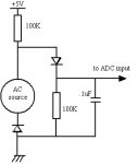
The measurement of very low AC voltages values needs to offset the rectifying diode voltage drop. This can be achieved just using passive components providing the AC voltage source has a small internal resistance. The attached circuit diagram will work assuming that the AC voltage source swings within the .6 volt of the diodes, that it can withstand a DC current of 10 microamp and that it is floating (no connection to ground). The filtering capacitor value is indicative since it depends on the AC frequency. In case of 50Hz increase it to 1 microF.
Good luck
Good luck
Use "Manage Attachments" button down below to upload to Forum, or use a Host like www.tinypic.com to upload and copy a link.
If it doesn't work then (again) use a Hosting site like www.tinypic.com
and paste the link...

OR Click the "Post Reply" button and you get THIS PAGE.
Then.... click "Manage Attachments"
and paste the link...
OR Click the "Post Reply" button and you get THIS PAGE.
Then.... click "Manage Attachments"
Attachments
-
 100.9 KB Views: 2
hippy
Ex-Staff (retired)
Click on the 'down triangle' for Quick Reply, then click on "Go Advanced". Probably quicker ways ( see above ).
For adding an in-line picture you can just specify the image within [img]...[/img] tags -
[img]http://www.somewhere.com/something.gif[img]
That will then appear in the post rather than as a URL or link.
Ideally don't in-line huge images as everyone visiting the page gets hit with a huge download.
For adding an in-line picture you can just specify the image within [img]...[/img] tags -
[img]http://www.somewhere.com/something.gif[img]
That will then appear in the post rather than as a URL or link.
Ideally don't in-line huge images as everyone visiting the page gets hit with a huge download.
Last edited:

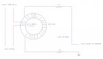
Right yes I'm drawing show here, readadc read AC input when turn on current around 2400 watts through core series input primary and secondary output 0.05Vac and then when turn off no current cause secondary no volt input PICAXE alert something like that. Not read for level low and high, its trigger only like PICAXE output on and off. Anyway, what diagram circuit is right or need add or change better the way?
Attachments
-
 57.2 KB Views: 37
Last edited:
BeanieBots
Moderator
Oh, it's a mains load "ON" detector!
Stop faffing about with silly low voltage AC signals and use the correct transformer winding ratio. More turns on the core, half wave rectifier, maybe a zener to clamp overload voltages and use a digital input.
Stop faffing about with silly low voltage AC signals and use the correct transformer winding ratio. More turns on the core, half wave rectifier, maybe a zener to clamp overload voltages and use a digital input.
If you want to sample ac you probably ought to know about the Nyquist-Shannon sampling theorem which says you have to sample at twice the ac frequency if you want to get proper readings. And also understand about aliasing. And then turn your samples into information. If you take a sample at the zero-crossing you might think it was off. If all you want is to detect presence of ac then perhaps better to make some dc and measure that.
If he's just looking at switching he can just sample for peak or a threshold (averaged or not)
No need for all that Nyquist stuff is there?
Besides, most people get that all wrong anyway. Best read up on it in relation to continuous and instantaneous waves.
To do proper voltage/current monitoring your ADCing needs to be far, far faster than the mains frequency. But I don't think that is needed here hopefully.
Agreed, if it is just on/off and he does not get the zero-crossing. A resistor, a diode and a cap should do it, maybe also a zener to protect the adc. Though I can't say I like the idea of a novice making a mains current transformer. Or I'm wondering if perhaps there would be enough flux to operate a reed relay if one side of the mains supply (10A) was wound round it. Then you have complete isolation.
Agreed: why risk your nail varnish when you can buy a properly made CT for 50p?
I've given up cringing when people here go on about Mains.
I never know whether they are experienced or not, so I've given up being Nanny too. You can only say "Don't do it!" or "Be careful!" or "House Insurance" so many times before you get fed up.
I've given up cringing when people here go on about Mains.
I never know whether they are experienced or not, so I've given up being Nanny too. You can only say "Don't do it!" or "Be careful!" or "House Insurance" so many times before you get fed up.
Dippy, I think there's a new series of grumpy old men coming up, maybe you should audition
For measuring AC currents in quite a safe way, why not take a look at the Allegro range of ACS71x series of hall effect sensors. They give of a voltage between 2-5v that is linear to the current going through it.
Can I have permission to be slightly grumpy? When is someone going to sort out a tutorials section, this is another example of a question thats been answered quite often in the past.
Miles
________
Mercedes-Benz C216
Last edited:
If I have translated that correctly, I think someone did that on this Forum years ago. I thnk Vroom forgot the word "Hall" in his/her post. The method is used by a number of big(ish) manufacturers.
Ciseco's suggestion is the easiest if you want to measure current.
Maxim make numerous current sensing devices with a range of specs.
Get one of those and you'll be up and running by elevenses.
I'll do a Tutorial entitled: All talk and no Action
Ciseco's suggestion is the easiest if you want to measure current.
Maxim make numerous current sensing devices with a range of specs.
Get one of those and you'll be up and running by elevenses.
I'll do a Tutorial entitled: All talk and no Action
Last edited: