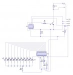
Picaxe Amps

hippy

Technical Support
Staff member
The diode in the circuit diagram isn't their i removed it while testing there is just a link wire there.
Then there will be a short between 12V and the 0V through the transistor when it conducts. I'm surprised the transistor hasn't disappeared in a puff of smoke leaving just its legs behind.

Remove the wire link.
 

nbw

Senior Member
Don't forget also to put a 2.2uF tantalum cap - watch the polarity - on the Vsupply lead going into the anode ends of those LEDs... if you get too much current sucked through there it will upset the LM391x you're using and you might get nasty oscillations. The chips are very sensitive to it. Certainly doesn't hurt regardless of whether you run it in bar or dot mode. You could lose the resistor going into the Vsupply for the anodes also - the IC handles the LED current - from memory it is 10x the current sensed from pin 6. Also make sure all of your grounds in that part of the circuit head right back to pin2, i.e. don't stop along the way and drop or collect some voltage.

Good luck.
 

SKL BOI

Member
rite now i have put that diode in it works in theory im getting voltage from the output terminal but when i plug both the fans in nothing happens!!

Sorry i didn't see that before.

If i use a tantalum cap then do i have to use the resistor or not?

I also want to run led's off of the picaxe 14pin chip would the tantalum cap do it for 3 led's from the pic too?

DO you know how to get it in bar mode with my circuit because i can't?

Its an lm3914 chip.

Im going to use a 14pin chip on the final board so which output is the PWM?
 
Last edited:

hippy

Technical Support
Staff member
Im going to use a 14pin chip on the final board so which output is the PWM?
Legs 5, 6, 7 or 8 - See PICAXE Manual 1, page 80.

I would strongly recommend that you get your circuit working with the 08M before moving on to the 14M. Otherwise you are just adding another level of unnecessary difficulty in getting things to work and wil be making it harder for people to help you.

rite now i have put that diode in it works in theory im getting voltage from the output terminal but when i plug both the fans in nothing happens!!
Have you tried with a LED + R As previously suggested instead of the fan ?

It is still not clear how you mean by "getting voltage from the output terminal". One of the fan connections is +12V and should rread as +12V, the other connects via the transistor to 0V. There should AFAIK be no voltage seen on that terminal with no fan connected. That terminal is a switched current sink to 0V and does not generate voltage. What voltage level are you reading ?

It is still not clear what does and does not actually work, so please do this -

1) Disconnect any fan, leave the two terminal disconnected.

2) Find a LED+R and check it works and lights reasonably brightly between 5V and 0V of your board.

3) Disconnect the 0V end of your LED+R and connect it to leg 5 of the PICAXE 08M ( Output Pin 2, the PWMOUT pin ). Leave the other end connected to 5V.

4) Download and run the following program -

#Picaxe 08M
Do
Pause 500 : PwmOut 2,255,255
Pause 500 : PwmOut 2,255,25
Loop

5) Does that give two alternating levels of brightness; bright and dim ?
 
Last edited:

hippy

Technical Support
Staff member
no it stays the same brightness. im using the 2n7000 transistor at the moment.
Did you connect the LED+R directly to leg 4 or have you got it connected between the terminals or to the transistor ?
 

SKL BOI

Member
After the transistor both the wires for the output. Ill try it before the transistor.

the LED doesn't light up with the resistor in-line the negative to the negative and the positive to the pic output nothing happens.
 
Last edited:

MartinM57

Moderator
so if i have a 22k followed by \ 10k down to negative this will fix that problem?
That sounds suspiciously like you have the download circuit in place (those are the resistor values in the download circuit), but you haven't shown us that in your circuit diagram :(

Do you have the download circuit in place? If so, then you don't need to make any changes to Serin and you have some other problem.

I really think you still still go back to basics:
- draw an accurate, simple and minimal circuit diagram (but including the download circuit if you are using it) of the fan control part of the circuit
- post it here so we can look at it
- build it on a breadboard
- put some really simple on/off code in the PICAXE (like what I suggested above)
- test it with your voltmeter at
a) the PICAXE output pin (should be 0v and 5v alternately)
b) the collector of the transistor (should be 12v and about 1v alternately (EDIT: with the motor in place) - do you understand why?)
- if the tests are OK there's no reason why the fan shouldn't work

There's a lot of people putting a lot of effort into trying to help you here - I'm sure we're willing to continue but you need to help yourself as well ;)
 
Last edited:

SKL BOI

Member
no im not putting the download circuit on the board im doing that on a separate board but as i quoted it said to be pulled to 0v so i thought that meant it had to have the resistor in it like on the download circuit but now i know it doesn't. That will give me a hell of allot more room.

what transistor do you suggest i use while doing the tests again.

Thanks
 

SKL BOI

Member
ok i got between 0-5v on the pic output and 0-12v on the power output i plugged it into a fan and nothing happened! i have another fan out there but i needed to solder the cables into the cables attached so i did but i forgot to turn off the power so i blew up the transistor. will a bc546 do as i can get them tonight i know that maplins don't have any more because i took their last of the bc639.

This is what i don't iunderstand everytime i put the multimeter on it it should work but then i plug the fan in and nothing happens! GRRR
 

Attachments

Last edited:

hippy

Technical Support
Staff member
Have you tried with the LED+R yet ?

Also, "i got between 0-5v on the pic output and 0-12v on the power output"; I don't understand what this power output is; there is no power output per se.

What / where exactly are you measuring ?
 
Last edited:
Top