Picaxe 28x2 Autopilot for Snoopy's Trans-Atlantic Robot Boat

Robin Lovelock

Senior Member
Hi Guys. It must be years since I posted on this Forum - I hope it sends me an email - too many to visit ? :)

I'm hoping to find anyone, at a sensible price, to provide an assembled Picaxe 28x2 board to minimise work on Snoopy's boat repairs.

First the "Snoopy" page on www.gpss.co.uk/autop.htm - tells you what this is about. e.g. last year's (2022) Atlantic Attempt - 6 weeks at sea ! :)

Then "Blog10" on www.gpss.co.uk/rbblog10.htm with latest on repairing Snoopy's boat for this year's 2023 Attempt.

The "Design" page is on www.gpss.co.uk/rbdesign.htm - yes - I'm still sticking with that old Picaxe 28X2 autopilot - with WELL TESTED software :)

In recent years I've "fallen in love" with the MicroMite - that needs someone ( in China ? ) to manufacture.
But PLEASE DO NOT GET DISTRACTED. Very easy to program, and I have (free) Autopilot software, BUT it has not been tested - that takes TIME.
I may as well provide the link here, in case someone like Hippy want to pursue it: www.gpss.co.uk/micromit.htm

I MAY have a spare Picaxe 28x2 assembled board somewhere here, but assembly takes time, and "there are just not enough hours in the day" :)

Ideally, I'd at least like it as I once purchased, with the chip on the board with components.
If someone is happy ( at a sensible price ) to add those standard Futaba leads ( makes testing easy ) so much the better.
If purchase is done via ebay and paypal, it covers the bases such as mutual satisfaction on the "contract".

If you visit my "Home" page on www.gpss.co.uk it is an "Open Book" on us and what we are up to.
e.g. that Youtube channel and other things that take up my time.

Take Care
Robin
www.gpss.co.uk
 

Robin Lovelock

Senior Member
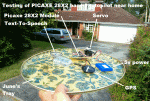
Hi Guys. I've just updated "Blog10" on www.gpss.co.uk/rbblog10.htm with three photos, two of which show the corroded Picaxe 28X2 subsystem.

This was after a telecon with my friend Terry who may join this forum, or at least look at it. He was looking on the picaxe site, but the photos may help in identifying what I purchased years ago, and MAY still be available. Many Thanks in advance for any help. Sorry if 3 photos not added here.

Robin
www.gpss.co.uk
25789rbb10b1.gif
 

Attachments

Robin Lovelock

Senior Member
Hi Buzby ! Many Thanks ! It's so long ago, I can't remember who you are, but great to see an email waiting for me when I got back from our village, visiting Indian friends. Yes, this was a topic discussed, along with taking a day trip down to Boscombe :)

Before answering your question in more detail, let me say I've just made a major update to the "Snoopy" page on http://www.gpss.co.uk/autop.htm after I saw that things like our August 2022 Attempt were not clearly presented near the top, and further down. This then links into the very relevant "Blog10" on www.gpss.co.uk/rbblog10.htm which will soon have more about the replacement of the Picaxe subsystem.

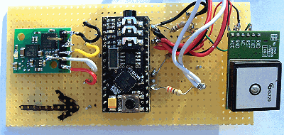
I took a better photo, of the Picaxe module, which you see in the top right hand corner of the middle picture. Not had time to add that yet. But at least it should help anyone, including myself, friends, or whoever, at least identify what boards, chips, and components can be used - and how much time it will take - time is money ! :)

But no point starting, before, whoever puts the hardware together, can at least have a ready program to load into it. I did it years ago for the Micromite, but hopefully, I can simply upload, into my webspace(s) my autopilot program, and it can simply be loaded into the chip. At least, if they add a servo to the correct pin, it should do the correct "waggle" on startup. It's then a question of if they hang the text-to-speech output onto an (expensive) TTS module, or some other terminal. i.e. to see version of software, and - if an RS232 GPS is added - the "commentary" as it tries to steer to it's target.

I'm very happy if anyone chooses to put the software into their own little robot boats - but I do not recommend use of this software if any change is needed. e.g. it will only work west of 0 longitude (Greenwich Meridian ) and (probably) from the English Channel to it's target: Mayflower 2 moored at Plymouth, MA, USA. It will recognise Bray Lake near Maidenhead, which is it's default test route.

The Micromite on www.gpss.co.uk/micromit.htm is VERY different, and very easy to program, but I don't have the few hours or days needed to TEST the updated (public) autopilot properly - unlike my Picaxe Autopilots - with simulators and - of course - LOTS of sailing inland, then at sea.

LOTS of words from me, but it saves time in the long run, since the same postings get passed to friends like Terry ( part of Team-Joker ) and overseas on my ROBINLOVELOCKSFRIENDS Google Group.

Good if you can release anything about yourself, like at least full name, country, nearest city, year of birth, etc. Best if already public I guess ? :)

Don't forget I may share these postings with anyone ;-)

Many Thanks again.
Robin
www.gpss.co.uk
rbb10p1.gif
 

Robin Lovelock

Senior Member
Just to say I've just ordered two of those AXE201 Picaxe 28X2 modules, by 1st class post, at ~ 36.50 GBP - worth the risk, if any :)
Would have been quicker, but it took me a while to get through the order form process - red text kept appearing.
Risk ? I'm happy to take it, but it looks like the same module that I got years ago - several, of course.
I can always pass to a local friend to spend a few hours(?) getting it "off the ground" ;-)
Thanks Buzby. Look forward to your next posting - depending on what time zone you are in ;-)
Robin
www.gpss.co.uk
 

Robin Lovelock

Senior Member
Hi Guys. This discussion has done me another favour - I see I needed to upload the few .BAS (source code) files into my newer web hostings.

I think the latest version of my Picaxe Autopilot is version "Romeo" on www.gpss.co.uk/ap28x2r.bas and the first few lines are these comments ..
QUOTE
'AP28X2R.BAS 01Dec17 "Romeo" of Snoopy's Picaxe 28X2 Autopilot Software. (c) Robin Lovelock www.GPSS.co.uk
'AP28X2R.BAS 06Dec17 "Romeo" rudder gearing constant MAXDERR = 30 to 60 after today's test
'AP28X2R.BAS 01Dec17 "Romeo" Only change is rudder gearing constant MAXDERR = 120 to 30
'based on
'AP28X2Q.BAS 31Jul17 "Quebec" Correct cross trackj error by comparing W24 CBWP Course Between Way Points
'AP28X2P.BAS 16Jul17 "Papa" remove spoken range bug when ~ 100m E-W heard on 12th July 17.
UNQUOTE

Any version should do the same things, regarding receiving NMEA GPS data, driving the rudder servo, and output to Text-To-Speech (TTS).
i.e. enough to check the hardware module is complete. But good to have the latest TESTED version, so it can be popped into a boat :)

I must put a little of this onto my "Blog10" - if and when I have the time :)
Robin
www.gpss.co.uk
 

Robin Lovelock

Senior Member
Hi Guys. I've just ordered another 4 of those Picaxe 28X2 modules Digby pointed me at, covering the bases for this email sparking too many guys buying the same thing, or the product not becoming available in the future. Some of you may wish to try it in a robot boat, and - if you try my software above - it will not work everywhere. The attached images, from places like my "Snoopy" and "Blog10" pages may help.

Yes Digby - I am looking for someone to offer - at a sensible price - those modules added to a veroboard with flying Futaba (Radio Control) leads - suitably labelled ( even if just paper, pen, and selotape ) such as "Power", "Rudder Servo", "GPS", "TTS". Some of you guys may decide to build some for yourselves, for themselves, children, or grandchildren :)

I'll end with Digby's VERY useful posting, and those pictures.
Thanks in advance
Robin
www.gpss.co.uk
"Snoopy" on www.gpss.co.uk/autop.htm
"Blog10" on www.gpss.co.uk/rbblog10.htm
"Design" on www.gpss.co.uk/rbdesign.htm

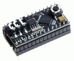
The 28X2 module looks like the AXE201, see here : https://www.picaxestore.com/picaxe/picaxe-chips/picaxe-modules/axe201

Are you looking for somone to assemble the veroboard circuit that the AXE201 is mounted on ? 2579425795
 

Attachments

Buzby

Senior Member
No problem, I've been called worse before !.

How soon do you need these devices constructing ?.
 

Robin Lovelock

Senior Member
Thanks Buzby - me too - I get called all sorts of things. "Mad ex-NATO Scientist" is just one :)

I'll probably make up one myself, as in the description below. So that's up to you. My guess is that
this first step, of making the veroboard assembly, with flying leads, might take me an hour of carefull soldering. Years since I made one :)

It's a couple of weeks before our Sicily holiday ( 1st to 14th June ) Ref "Holiday" page on www.gpss.co.uk/holiday.htm and it will be good
if I have at least one soon. But I guess it is obvious there may be other benefits of the 28X2 being used by others in this sort of way ;-)
Yes, I'm relaxed about anyone knowing when we are away and where to: for years I even let others track us, and may meet up ;-)
Anyone thinking of visiting while we are away ( just June and myself ) should see the "Health & Safety Warnings" on my videos ;-)

By "device" I guess we mean just the veraboard, about 3" X 1 3/8", with the Picaxe 28x2 module mounted on it,
plus 5 groups of 3 pins, for the 1) wires from the module, and 2) sets of Futaba flying leads ( red +5v, black 0v, white signal ).
Gender of plug depends on what plugs into it. e.g. Female to receive male providing 5v power from a Radio Control 5v NiMhd battery pack,
and Female to receive plug from a standard Radio Control servo. For the boats, I use the Acoms AS-17 Servo, used to drive the rudder.

As it happens, the servo is the "weak link" in Snoopy's Robot Boat design, where reliability is critical. BUT, after years of testing alternatives,
such as brushless servos, we have not found anything more reliable that is suitable. e.g. MTBF of typically 3 months, when receiving
a typical rudder movement every 7 seconds. Also low power draw when idle ( between those 7 seconds ). Obviously standard servo signals
and power levels. Best if similarly compact, so can be fitted into the box.

While I'm writing these words, there is obviously a big difference, particularly on price I ( or others ?) will pay, if the board comes with
a GPS - easy to add, since signals are compatible. They are not cheap, if the same from Globalsat, but other chipsets may be better.

25797

The same can be said for the Text-To-Speech units - but let's keep it simple, and stick to just the veroboard module above.

I may put this text up onto "Blog10" on www.gpss.co.uk/rbblog10.htm if it helps, but I think it better just to stick to actual progress.
e.g. after I've fitted the servo to rudder into the boat, and connected the working Picaxe 28X2 assembly.
e.g. confirm I have the rudder linkage geometry correct - it's changed a lot over the years - including use of servo reversers :)

We are not long back from a nice trip to an NGS garden, north of High Wycombe. Anyone interested can see where we went by tapping
on the Spot Trace tracker links. There will probably be another video on my youtube channel - but that might be days.

Thanks again.
Robin
www.gpss.co.uk
 
Last edited:

Robin Lovelock

Senior Member
Hi Guys. Some may be interested in the extract below from my "Design" page on www.gpss.co.uk/rbdesign.htm

I've received the 28X2 Modules and have ordered two jack-USB software load cables, so my local friends and I have enough - even if I find my old ones :) I'm now making sure that I have all the components, including veroboard, resistors, and transistors such as BC635, to build and test several Picaxe 28X2 based Robot Boat autopilots. PLEASE NOTE THAT POWER SWITCHING AND THE COMPASS IS NOT NEEDED. That was early experimental work, and, subsequents tests meant we stuck with the more basic design: the performance benefit was not worth the extra bits - more things to fail. RELIABILTY is the key for this project. As that American Avionics Engineer said, many years ago, "KISS = Keep It Simple, Stupid" ;-)

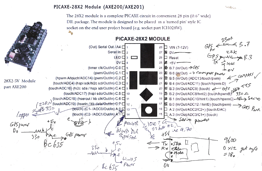
I found my handwritten diagram invaluable, so I can now start collecting and ordering bits, before getting my soldering iron out, then loading that autopilot software into the Picaxe 28X2. Yes, I'll find out what version it was then. Maybe "Romeo" ??? All on "Blog10" on www.gpss.co.uk/rbblog10.htm

I'll end by trying to paste that extract in below. I'll also attach the important printout in rb28x2xx.gif in case it does not appear.
Robin
www.gpss.co.uk
25800
e. Alternative Designs ...

PICAXE 28X2 Module with Compass and Skylab GPS
Here are some ideas on how my design may eventually get modified or changed - including back to some of my early ideas from my first thoughts in 2008, like the electronic compass. Thanks to those whose emails have spurred these thoughts.

e1. electronic compass ? Bigger computer ? Power switching of sensors ?
During August 2013, experimental work was started using an electronic compass. Details of this work are on the Compass page, which was expanded in July 2014, after starting work on a much better, tilt-compensated, compass. This work was closely coupled with use of a different, 28X2 Picaxe computer, with twice as much memory. Experiments were started on techniques such as "Power Switching" the sensors, such as compass and GPS, and even the servo, that moves the rudder. Another old page that may receive attention again soon, is the Wind Direction Sensor page. We got the solution to work, including "tacking logic" in the software, but after trials, the wind direction sensor was removed, because the power it consumed was not justified by significantly better upwind sailing performance.
PICAXE 28X2 experimental connections
This experimental work is not relevant to the existing design, used in boats 8, 9 and 10, but it might be used in future boats. If you go back to my earliest thoughts in 2008, you will see I was thinking of a flux gate compass, to sense where the boat is pointing, for the autopilot steering. Our simple GPS solutions use, instead, the direction the boat is moving - which is not the same thing. Things like the tide can "confuse" the autopilot. We can live with this design limitation, but, if we wanted to perform a sailing mission such as "sail around the Isle of Wight" - we would need to have an autopilot that would handle the tide better. However, the main benifit of the compass is probably to allow power switching of the GPS, with the consequent reduction in power consumption, numbers of solar panels, weight and cost of the boat.
The rough notes on the right were put here, in case I lost the paper original. Click on it for the bigger version.
I would describe the current experimental work as "research" rather than "development" :)
Footnote on Saturday 25th October 2014: I started some tests, picking up from work in August. Right now there are three 28X2-Compass autopilots: one in boat 6, one in boat 11, and one on the tea-tray. Only the tea tray autopilot has the GPS and servo power-switching changes. Tests with a milliamp meter confirm that the first two still consume current in the ballpark of 60mA. i.e. switching from a Picaxe 2M2 to the 28X2 does not make a significant increase in power consumption: the Picaxe draws less than 5mA.
After fixing a short between pins 27 and 28, initial tests indicate power consumption in the ballpark of about 20mA when the GPS is off, and the boat is using compass steering, and about 60mA when switching on the GPS for a "navigation check". The better BR355-2 GPS only seems to need a second or two of power, before it tracks, and is switched off. So, if off for even 30 seconds, the average current for the GPS will drop to less than 10% of it's normal ~40mA.
Most of the 20mA is for the servo, so further reductions might be made by power switching of this - already working back in August 2014. But for now, we will keep it simple, and stick with just compass and GPS power switching.
Looking at the last experimental software change (AUTOPX1.BAS dated 22 Aug 14), it seems, for our first experiments with GPS power switching, the following rules are used: GPS power kept on if within 30m of target; switched off for 10 secs if 30m to 50m; switched off for 30 secs if further than 50m from target. The compass is used for steering when the GPS is switched off. These rules can easily be modified, after we get the power-switched autopilot working as it should. i.e. still doing it's job, tested on Bray Lake, and with significantly less power consumption than the existing 8M2 based systems.
So, in conclusion, far more experimental work is needed, including tests on Bray Lake, but it does look as if power switching of the GPS can reduce the autopilot power consumption by 50% or more. The boat 6 autopilot has been modified to include GPS power switching and the latest Picaxe software. The old BR353 was replaced by the later BR355-2 and we saw an immediate improvement in the time needed to start tracking, after switch-on: from about 60 seconds (indoors) to nearer 2 seconds ! This will be needed if the GPS switching is to be exploited.
Remember that this is all "background experimental work", while we wait to launch Snoopy in boat10 !
 

Flenser

Senior Member
Robin,

A detail I've thought of that Buzby, or anyone else, will need to know if they plans to build one of these boards.

There is a circuit diagram on this page that shows the 08M2/28M2 running of two 4.8V battery packs connected in parallel.
The image in post #11 above has a line drawn next to pin 25/5v on the 28M2 module but there is no description of what that line represents.

Is the AXE200/201 module powered by the 4.8V battery packs connected to pin 25/5v and are the servo, the gps and the tts modules also all powered by connecting their V+ to the 4.8V battery packs output?
 

Robin Lovelock

Senior Member
Thanks Flenser. The short answer I think to your question is "Yes", all things are using the same shared "4.8v" ( ~ 5v ) supply, via the industry-standard Futaba Radio Control leads. It's easy for me to be confused with other products, that use 3v, and so I would include the transistor like 5v->3v thing.
But, if I am correct, and the Picaxe 28x2 module uses 5v, then it is all very simple.

This is topical for me, because, among all the other activities, I'm getting things like veroboard, pins, wire, and other things like resistors, so I can assemble then test the first board. Starting with the 5v R/C battery, servo, and maybe, soon after, TTS and GPS. First job, will of course, be loading of my autopilot software into the 28x2 module, using one of the cables, I now have from the Picaxe shop.

I guess the diagram you refer to is what I just took a look at, on my "Design" page www.gpss.co.uk/rbdesign.htm See below.

Reason for my delay ? Coffee here after the pub with two of my Grumpy Old ( Engineer ) friends. Two others were at the pub.
Anyone intertested could have tracked us with those links on my "Blog10" page www.gpss.co.uk/rbblog10.htm

Thanks again :)
Robin
www.gpss.co.uk
25801
 

Flenser

Senior Member
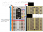
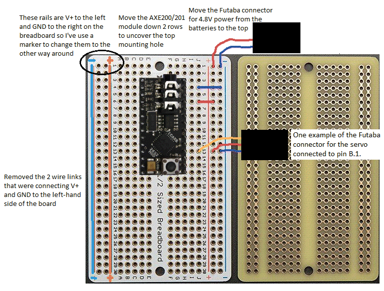
It occurred to me that the layout of the power rails on a breadboard along the side of the pins can naturally provide the signal, V+, & GND in the correct order to to connect the Futaba connector (i.e. V+ in the middle, GND on one side and the signal to/from the 28X2 module pin on the other side) which could make connecting all the Futaba connectors easier than on a stripboard.

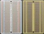
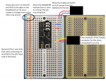
There are PCBs made with the same layout a breadboard so here is an example of how you could create your device with only links to connect power to the power rails on each side of the PCB and from the power rails on the right-hand side to the 28X2 module.


The breadboard PCB has V+ to the left and GND to the right on both sides of the PCB so I've mimicked using a marker on the left-hand side of the PCB to switch V+ to the right and GND to the left.

The example above is a premium PCB that was easy to find so it might end up being a matter of how cheaply you can buy PCBs with the breadboard layout delivered
.25815

There are other, plainer. versions like this PR700 model, that could be cut up to make several devices:
25803

[Post edited to replace the example layout with the V+ connection to the AXE200/201 corrected]
 
Last edited:

Robin Lovelock

Senior Member
Thanks Flenser - Brillant advice - I looked on https://www.picaxestore.com/picaxe/project-boards but need to look elsewhere ?

But first a diversion: JulianE: many reasons for that video sign-off with the important word being "we".
I guess what influence this most, was my distant relative James Lovelock who appears on several of my pages, particularly "Covid19" on www.gpss.co.uk/covid19.htm and "Grumpy" on www.gpss.co.uk/grumpy.htm - my paraphasing on his book "Revenge of Gaia".
He died on his 103rd Birthday last year, and you only need to play a video of one of those TV interviews to admire the guy.
He knew that Global Warming was gonna happen, whatever anyone does, had written it up, then moved on to other things, like AI etc.
And of course, as one gets older, losing friends and loved ones, "goes with the territory".
It is no coincidence that this reply is late, because of our time with another Grumpy Old Man and his wife.
Roy and I were workmates, in 1970, at Ferranti, working on Naval systems www.gpss.co.uk/ferranti.htm e.g. CAAIS.
We popped in and he gave me some scraps of similar board - but we spent more time looking at their garden, and fierce cat, Bovril :)

I may as well warn you, that my camera has a detailed photo trail, for some future video. e.g. combining socialising with testing trackers for Snoopy's Robot Boat. I've taken snaps of our screen of Flensen's posting :)

Now to the crux of it Flensen: if I can buy quickly, something like you describe, I will do it - probably at least 2 boards or more.
Ideally a link to the product - perfect if it is in the Picaxe store. I WAS thinking of starting on one, using the scraps of board from Roy,
maybe tomorrow, but if I can get them for 1st class post soon, maybe I'll wait. I think most of you are too far for a special car journey ;-)

So I'll get this off and see where I can get what you show: if a daft price, I may still buy it - but then everyone will know ;-)
Take Care
Robin
www.gpss.co.uk
 

steliosm

Senior Member
Robin, have a look at amazon.co.uk. If you search for "solderable breadboard" you will find similar products to what Flenser has proposed.
 

Robin Lovelock

Senior Member
Thanks Steliosm. I did a search as you suggested ( link is below ) and saw a LOT of boards. Good if someone can give me the link to the one that Flenser show clearly shows in his photos above. The link into Amazon after that search is below ...
https://www.amazon.co.uk/s?k=solderable+breadboard&crid=1U4WM2SMJETIV&sprefix=solderable+breadboard,aps,1024&ref=nb_sb_ss_ts-doa-p_1_21
... hope that works :)
I like the idea of buying on Amazon - I may use my wife June's account while she is distracted, playing or watching tennis.
Now back to what I was doing, working on information to go up onto "Blog10" later today :)
Thanks Again
Robin
www.gpss.co.uk
 

Flenser

Senior Member
Robin, also search ebay and search google (then click images and/or shopping)
Search for "breadboard pcb". You'll get a lot of hits for things like plain stripboard so look for something of this type with two power rails on both side.
Search for "Perma-Proto Half-sized Breadboard PCB" to search for the specific product I used for my example.
I'm suggesting doing a google image search because there are some hobby electronics companies that supply picaxe chips, arduino and Raspberry Pi boards, solderless breadboards, stripboard, etc. The UK has a much bigger population than Oz so I'd be very surprised if there were no hobby electronics companies local to the UK.

I've searched for "3-packs" because the price-per-board generally works out cheaper and you did mention creating more than one device.
This link is from Amazon.co.uk. There is no price displayed on the page I see but perhaps that is because I am from Au:
Improved my "google fu" to find one link to a UK hobby store.

My search of www.ebay.co.uk was not a success. All the matches for "Perma-Proto Half-sized Breadboard PCB" were from companies in the US and this link was the cheapest 3-pack, which was no cheaper than the amazon.co.uk hit and the delivery would probably be much longer.
 
Last edited:

Robin Lovelock

Senior Member
Thanks Flenser and Steliosm. I was about to say "Why don't you guys do the searching, to find the product shown in Flenser's clear picture above ? Few of us have the time :)" But Flenser, is that "3 pack" link what you used ? Anyone: just a simple link to ONE product that matches Flenser's piccy :)

Meanwhile, I've updated http://www.gpss.co.uk/rbblog10.htm with significant stuff about the Gotop solar tracker. Yes, I do occasionally "get my hands dirty" but I prefer others to do the dirty work ( or hard work ) for me ;-)

Take Care
Robin
www.gpss.co.uk
 

Flenser

Senior Member
Flenser, is that "3 pack" link what you used ?
Yes, the links in my posts #19 & #20 are to 3-packs of the same Adafruit Perma-Proto Half-sized Breadboard PCB that I used pictures of to create the example layout diagram in post #14.

Here is the image I started with to create my layout.
Without the AXE200/201 module, wires and comments I drew over the image you can clearly see the product name printed onto the top of the PCB on the left.
You can use the image on the left to confirm that the PCBs you buy are the same as the one I used for my example layout.
25804
 

Flenser

Senior Member
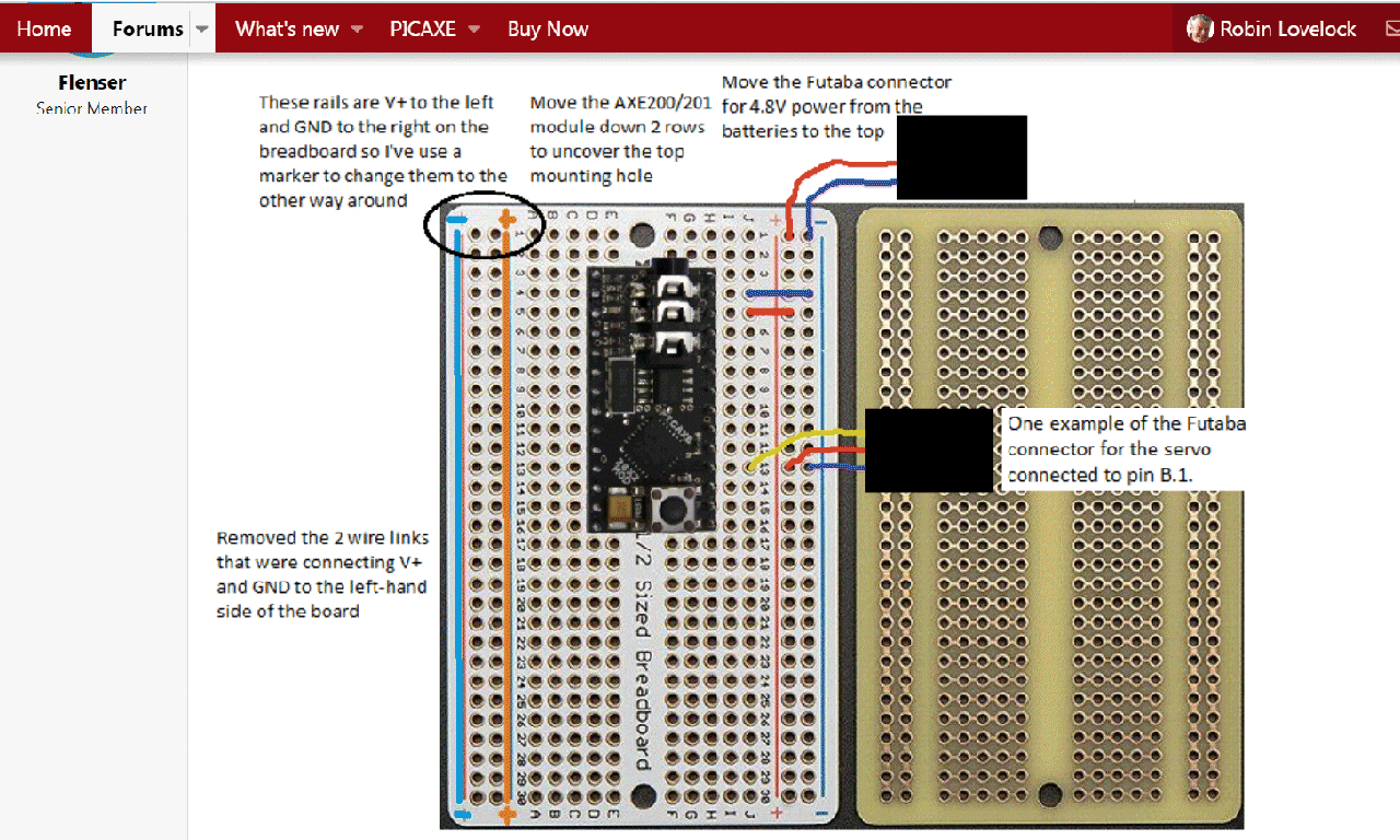
Here is revision 1 of my example layout.
Moved the AXE200/201 module down two rows to uncover the top mounting hole
Moved the Futaba connector for 4.8V from the batteries to the end of the power rails. This means I only need two links to connect V+ and GND to the other side of the board so there are now only 4 wire links that need to be soldered to the PCB.

25816

[Edited to replace the example layout with the V+ connection to the AXE200/201 corrected]
 
Last edited:

Robin Lovelock

Senior Member
Thanks Guys - Puurfect ! Have not been back long, after a day out, ending in our local Italian, but followed Flenser's link
and ordered the one that was not from the USA - typically takes longer. Then the link from Steliosm - even better - 'cos Prime
and quicker delivery - so ordered that too. So should have LOTS soon - AND they were ordered using my wife June's Amazon account.
She will probably send me a PAYPAL money request - or may react violently - as on my Covid19 page ( www.gpss.co.uk/covid19.htm )
after I gave her some "Saucy" underwear :) Photo attached below. Thanks again guys :)
Robin
www.gpss.co.uk
 

Attachments

Robin Lovelock

Senior Member
Hi Guys. This is "off topic" but I felt compelled to respond to Flenser's sign off quoting Rear Admiral Marsha Johnson Evans.
A remarkable lady: https://en.wikipedia.org/wiki/Marsha_J._Evans
This "pushed a few buttons" on me: e.g. my "Ferranti" page www.gpss.co.uk/ferranti.htm - naval systems like CAAIS
My first job after Uni' ( www.gpss.co.uk/cityuni.htm ) was the Data Link 10 software ( UK version of USN Link11 )
Then the radar tracking and other stuff. Then 1971 - 1980 in NATO it was air systems, USAF,RAF,RDAF etc www.gpss.co.uk/johnman.htm
Back in UK, at EASAMS ( www.gpss.co.uk/easams.htm ) it was all three services and Governments, UK and overseas...
BUT - back to Naval systems and the connections with the Pcaxe - used in Snoopy's Trans-Atlantic Robot Boats: www.gpss.co.uk/autop.htm
There are strong connections with the military Naval Academies. The "Microtransat Challenge" ( link at top of Snoopy page)
was conceived by Yves at the French Naval Academy, working closely with the guys at that on the USA side.
A project to get students interested in a wide range of disciplines, including technology, engineering, wind and tide, etc, etc.
I can understand why guys are cautious in revealing anything about themselves, but I first learnt from the Americans, in the 1970s that NOTHING is secure - all a matter of being as "Open" as possible, assuming you have nothing to hide ;-)
As it happens, despite my being called a "male chauvinist pig" I've got great respect for several women I've worked with.
One you may have heard of: Maggie Thatcher - helped us Brits clinch a 1 billion GBP deal in Malaysia vs the Yanks ;-)
Enough wittering from me. A video is brewing for release tomorrow maybe.
Yes, some of your good pictures will be in the photo trails - but well tucked away :)
Tonight we bumped into an old (1970) Ferranti buddy at our local La Sorrentina Italian.
It's a small World :)
Robin
www.gpss.co.uk
 

Attachments

Flenser

Senior Member
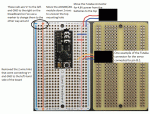
Revised my layout a second time.
If you are not using the power rails on the left-hand side of the board then the wire links connecting them to the rails on the right-hand side are redundant. So there are only 2 wire links that need to be soldered to the PCB,
25818
 
Last edited:

Flenser

Senior Member
Robin, in the original versions of all the layouts that I posted I had V+ connected to the wrong pin on the AXE200/201 module.
I have replaced the layouts in all my previous posts with corrected versions.
 

Robin Lovelock

Senior Member
Thanks Flenser. As I've said before, I'm happy to pay a sensible price, for one or two boards, loaded with my software, which may save time at this end. It should be easy for anyone to test at least the rudder servo output. BUT, more importantly, I've taken the liberty of including your picture, with others I found this morning, and an important update to near the end of "Blog10" on www.gpss.co.uk/rbblog10.htm I've included a link back to this Picaxe Active Forum. I'll attach some of the pictures here, to give a flavour. This has delayed what I was hoping to do today: getting another Youtube video up - and this activity is one small part of it ;-)
Thanks again
Robin
www.gpss.co.uk
2581925820
 

Flenser

Senior Member
Robin, you probably need to update your blog10 page. Your page has the original version of the release 2 layout diagram in my post #27 with V+ connected to the wrong pin on the AXE200/201 module.
 

Robin Lovelock

Senior Member
Thanks Flenser. Doh! as Homer would say :) Will do. Doing this reply on a Chromebook while Study PC busy processing what might be a youtube video uploaded later today. Something like "Visiting Guys & Testing Trackers with June & Robin Lovelock of Sunninghill". Will have a LOT on it, including stuff relevant to this discussion. Hopefully I can plug it into "Blog10" AND make that important correction. No harm in you posting the image again, so I'm less likely to make a mistake. I found it a bit difficult to crop the screen image, but got the important stuff. Lots more stuff arrived here, like boards and pins. Even if someone does not want to offer a board to me, at a sensible price, including P&P, they can always say their estimate of how much of their time needed to do all the work, including it going off in the post. I'm guessing for me it will be even longer :) Time is money, but for me and many I know, "there just aren't enough hours in the day". You will gather that from the video :)
Thanks again
Robin
www.gpss.co.uk and "Blog10" on www.gpss.co.uk/rbblog10.htm - if I can do this without the mouse :)
 

Robin Lovelock

Senior Member
Hi Guys, particularly Flenser. Is the the correct image in picaxeyy.gif that I should be using near the end of my "Blog10" on www.gpss.co.uk/rbblog10.htm ? I cleared my Chrome cache and made a better job of copying all the image. I can update "Blog10" in a few hours, when I add the youtube video - which is why I got upafter a few hours sleep - and will be off the bed for more soon :) I guess some of you may be on very different time zones. Take Care. Robin. www.gpss.co.uk - sorry for any weird layout of this text. should have added the image after I wrote it :)25822
 

Robin Lovelock

Senior Member
Thanks Flenser. I've just updated "Blog10" on www.gpss.co.uk/rbblog10.htm and I'll try and paste the update after my words and sign off here.
As I say, I can't see differences, but perhaps that's my eyesight, or - more probably - lack of browser refresh or clearing caches somewhere ? :)
Anyway, thanks again, and there may be a brief glimpse of this Picaxe forum dialogue in that 55 minute video now on Youtube :)
For anyone interested: I repeat my request for estimates of cost or just hours of effort.
For me, the time spent in putting this into the Public Domain is worth the time ;-)
Take Care
Robin
www.gpss.co.uk
Sunday 21st May 2023: Below is a picture from Flenser on the Active Pixaxe Forum . Then his correction. Same ? Thanks Guys :) Few will play this 55 minute video :)
Picaxe 28X2
Picaxe 28X2 Flenser
Youtube video Meeting Guys and Testing Trackers
white strip
More details here in due course :)
 

Robin Lovelock

Senior Member
Phil's Boat uses an Arduino rather than a Picaxe, but some of you guys may have an interest in this video, since much relates to Team-Joker and their Pickaxe-based Snoopy Robot boat. Here is the video now on Youtube ...
is a 22 minute rough cut video, including the trail of photos shot by Robin Lovelock on Monday 22nd May 2023. Most show the journey, to Chesil Beach, near Weymouth, to meet Phil Smith, from Cambridge, with his Trans-Atlantic Robot Boat, known as "Phil's Boat". You will see Team-Joker friend Peter, and others, such as the Bansal family, back in Sunninghill village. Trackers relevant to many things are seen tested. Robin includes a relevant clip from his recent "May Press Release" video near the end. e.g. Snoopy's 2012 Attempt BBC TV Publicity, and Robin's wishes concerning the DVLA and being banned from driving :) Then, Robin's usual "wrapping up" of the video at the end. i.e. Look after yourselves, Stay Safe, and enjoy life while we can ;-)

Robin
www.gpss.co.uk and Snoopy on www.gpss.co.uk/autop.htm
 

Flenser

Senior Member
Robin,

Looking at your hand written notes on the PICAXE-28X2 MODULE pinout image in your post #29 I see that you have a 330 ohm resistor on all the signal pins.
Adding a 330 ohm resistor to these pins on the PCB is something that is easy to do for the pins down the right-hand side of the 28X2 module.
Is a new layout with 330 ohm resistors on the signal lines down the right-hand side of the module something that you would be interested in?
 

Robin Lovelock

Senior Member
Yes Flenser, I am certainly interested in any build of the Picaxe 28x2 based Autopilot module. I am assuming that the module I ordered, and received, after Buzby's good advice, are identical to those 28X2 modules I used in Snoopy's boat for years. i.e. pin connections and need for things like those resistors.

It is usually the case that a "first build" for anyone needs to be given a good test, leaving running for hours or days, to ensure the chip is not overheating, etc. I think the documentation on my "Blog10" www.gpss.co.uk/rbblog10.htm is clear - I hope it is correct ! :)

I repeat my request for anyone to give an estimate of how many hours(?) they would take to build one or two ?
If they can give a firm fixed price, so much the better :)

Sorry for delay in this reply: yesterday was down near Weymouth, seeing Phil Smith and his Robot Boat, and today it was in London, getting my new passport - no probs - and then lovely hours at Greenwich visiting those historic places, so important for sea navigation. e.g. accurate GMT time :)

Thanks again
Robin
www.gpss.co.uk and "Snoopy" on www.gpss.co.uk/autop.htm
 

Robin Lovelock

Senior Member
Hi Guys. Check out
with a very small robot sailing boat.
Good speaking to some direct, especially if they fancy trying to try my autopiilot software on a pond somewhere,
or even at sea - so long as they have enough 5v power. e.g. solar panels :)
Take Care
Robin
www.gpss.co.uk
 

Robin Lovelock

Senior Member
This email below just sent to the MICROTRANSAT and ROBINLOVELOCKSFRIENDS Google Groups email list, but it follows on from direct emails from members of this group - thanks guys - you know who you are. Let's see if those links work OK ... particularly the last one - unsuitable for some ? :)

Hi Guys. I've just made a significant update to the "Snoopy" page on http://www.gpss.co.uk/autop.htm
with a link to that video that shows the early years of prototyping trials - with wise old men involved :)
Sadly, some, like Jack, Eric, and Brian, are no longer with us, but their pages are.
Off to a Birthday Pub Lunch soon, with some local Team-Joker friends - yes, Grumpy Old Men.
We are hoping for that Birthday Cake as you will see in the film "Under Siege"
I guess The Royal Marines have similar parties to the SEALS and US Navy Guys ? :)
:)
Take Care
Robin - and Snoopy :)
www.gpss.co.uk
 

Robin Lovelock

Senior Member
Well Done Picaxe Guys - for that "Saucy Seal" video being handled perfectly. e.g. warning about content.
This follow up is to say that the direct conversations, including with Microtransat guys, may lead to at least one
building that Snoopy 28X2 based autopilot, and popping it into a little radio controlled model sailing boat on a local pond.
Even without software change, it should, depending on lat/lon location, aim at the correct waypoint, so you can easily
see where, on the opposite bank (?) that would be. All this is on the "Snoopy" page:
QUOTE
Hi Guys. I've just made a significant update to the "Snoopy" page on http://www.gpss.co.uk/autop.htm
UNQUOTE
After you look at the routing logic pictures, you may see a bit of coastline, not too far away, for a Trans-Atlantic attempt.
BUT long before that, you will need to construct a suitable boat, even if you just pick up a discarded one from a local model boat sailing club.

I repeat my interest in anyone's estimate of how many hours to construct the autopilot, and thanks for feedback so we can check documentation.
As I've said, if they offer to supply one or two, so much the better.

Oh yes, I've now made our holiday in Sicily Public ( 1st to 14th June 2023 ) on the "Press" page www.gpss.co.uk/press.htm :)

I may remember to take the Gotop2 tracker with us to the pub - if you wish to track us : www.gpss.co.uk/rbblog10.htm
or go direct to https://110track.com/mod/share/index.php?su=EDF901FEF5E7B32275134DDF6DAB98CC

Thanks again for your help, thus far
Robin
www.gpss.co.uk
 
Top