PICAXE 18X vs 18M2+
- Thread starter davidwf
- Start date
")
hippy
Ex-Staff (retired)
Not sure how to really answer that, how you mean exactly.do I have to specify that they are i/p or o/p
You will need to set them as output to use them as outputs, but that is usually implicit in the command, HIGH or LOW etc.
westaust55
Moderator
To expand upon the information from hippy,
On the M2 and X2 parts most pins are inputs by default until specifically by commands set as outputs.
On the M2 and X2 parts most pins are inputs by default until specifically by commands set as outputs.
BeanieBots
Moderator
It's always good practice to tie down any floating pins, but the 18M2+ will still work fine if you don't. Unlike the 18X which MUST have reset tied high.
BeanieBots
Moderator
Correct, the 18M2 has no reset pin. Leg 4 is a regular (input only) pin.
BeanieBots
Moderator
Yes, that would be fine but 10k is more common as a pull-down as it has higher noise immunity but in practice any value between 330R and 1M would be fine.
BeanieBots
Moderator
I/O pins can be made outputs and on some PICAXEs you can configure internal pullups. Don't forget leg4 on the 18M2 is input ONLY.
You CAN leave it floating, but the OFFICIAL stance is to tie it down. I often leave them floating, the only time it is an issue is if you are looking for minimum current consumption or high accuracy ADC work. Each time an input changes state (a floating input will often synchronise with mains and toggle at 50/60Hz) it draws a significant amount of current from the supply for a very short duration. This causes unnecessary current draw and puts noise on the supply rail. Also, adjacent ADC pins will be slightly effected by a very small amount, especially if their source impedance is higher than recommended.
If you are short of space, not after ultra low power consumption and not using high accuracy ADC, then leave them off. But if anybody asks, say I said to fit them.
As for decoupling caps. Fit them. Always fit them. Never forget to fit them. If you don't fit them, don't come crying to me!
westaust55
Moderator
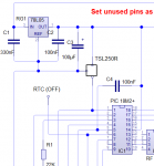
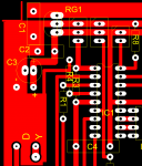
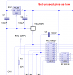
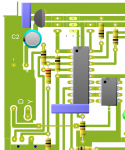
in terms of across the PICAXE chip by the schematic yes. C3 not shown in the PCB layout - should be as close to power supply pins as possible.sufficient decoupling ??
However on the 7805 output:
1. the electro/tantalum capacitor typically needs only to be around 10 to 33 uF (unless you are trying to support the 5Vdc line though momentary supply side voltage loss)
2. a 0.1 uF/ 100 nF ceramic capacitor is usually recommended to improves ripple rejection and transient response
See a typical 7805 datasheet:
https://www.fairchildsemi.com/datasheets/LM/LM7805.pdf (eg page 19)
and
http://www.ti.com/lit/ds/symlink/lm78l05.pdf (eg page 9 -where could be lower value for 87L05 parts)
but also see note 2 on page 3 under the Electrical Characteristics table.
Also see PICAXE manual 1 (http://www.picaxe.com/docs/picaxe_manual1.pdf) at page 26 - and yes that does show a 100 uF electro on the output side of the 7805.
Last edited:
westaust55
Moderator
The mentioned note 2 in the datasheet:
(a) recommended, and
(b) the minimum value
Irrespective of what is upstream of the input side the 0.01 to 0.1 uF ceramic cap on the 78[L]05 output is there to "help" prevent the local device going into high frequency resonance.
Note that is:(2) Recommended minimum load capacitance of 0.01 μF to limit high frequency noise.
(a) recommended, and
(b) the minimum value
Irrespective of what is upstream of the input side the 0.01 to 0.1 uF ceramic cap on the 78[L]05 output is there to "help" prevent the local device going into high frequency resonance.