picaxe 18m2 wind speed measurment device

aduy

Senior Member
hello all its been a while since i have posted here but i am once again working on a new project. im using an 18m2 to measure and output wind speed so that i can tell how fast i am going whilst on my longboard. i have the 18m2 hooked up to two 7 segment displays and i have the code written so that it will display the value of the variable b0 from 0 to 69(after 69 it shows "--"), i figured that i wouldnt be going any faster than 69mph or kph on my longboard so i just cut it off. npw if have the 18m2 read the voltage output by the fan it gives me a value, but i would rather use the existing tachometric signal(yellow wire) coming off of the fan to tell me what rpm it is running at, as presume that would be more accurate. another advantage is that there is no chance of the fan generating too much voltage and going out of readable range or damaging my circuit.

anyways my problem is that when i spin the fan by blowing on it it doesnt register to the chip and it just displays 00(i tested the display it works and it can display all the way from 00 to 69. i also tested the fan it is outputting the correct tachometric signal.)

heres my code and i apprediate any help(for the record it works correctly when reading from the adc on b.7, i just swap the code "count b.7,100,w0" out for "readadc b.7,w0)
Code:
disconnect


measure:
count b.7,100,w0
pause 1000
w0 = w1/10
gosub tens
gosub digits
goto measure


tens:
if w0=0 then gosub oh
if w0=1 then gosub ten
if w0=2 then gosub twenty
if w0=3 then gosub thirty
if w0=4 then gosub forty
if w0=5 then gosub fifty
if w0=6 then gosub sixty
if w0>6 then goto error1
return


digits:
w3=w0*10
w2=w1-w3
if w2=0 then gosub zero
if w2=1 then gosub one
if w2=2 then gosub two
if w2=3 then gosub three
if w2=4 then gosub four
if w2=5 then gosub five
if w2=6 then gosub six
if w2=7 then gosub seven
if w2=8 then gosub eight
if w2=9 then gosub nine
return


error1:
let pinsb = %00000000
let dirsb = %00001000
let pinsc = %00000000
let dirsc = %00111100
high c.3
goto measure


zero:
let pinsb = %00000000
let dirsb = %01110111


return


one:
let pinsb = %00000000
let dirsb = %01000100
return


two:
let pinsb = %00000000
let dirsb = %00111110
return


three:
let pinsb = %00000000
let dirsb = %01101110
return


four:
let pinsb = %00000000
let dirsb = %01001101
return


five:
let pinsb = %00000000
let dirsb = %01101011
return


six:
let pinsb = %00000000
let dirsb = %11111011
return


seven:
let pinsb = %00000000
let dirsb = %01000110
return


eight:
let pinsb = %00000000
let dirsb = %01111111
return


nine:
let pinsb = %00000000
let dirsb = %01101111
return


oh:
let pinsc = %00000000
let dirsc = %11100011
low c.3
return


ten:
let pinsc = %00000000
let dirsc = %10000010
high c.3
return


twenty:
let pinsc = %00000000
let dirsc = %11000101
high c.3
return


thirty:
let pinsc = %00000000
let dirsc = %10000111
high c.3
return


forty:
let pinsc = %00000000
let dirsc = %10100110
low c.3
return


fifty:
let pinsc = %00000000
let dirsc = %00100111
low c.3
return


sixty:
let pinsc = %00000000
let dirsc = %01100111
low c.3
return
another question: the count command can be used on any input pin correct?
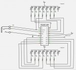
i will post a schematic soon :).
 

westaust55

Moderator
Can you advise what the value of the variable w0 is if you use the SERTXD command and output the value to the Programming Editor Terminal display (access with [F8] ).

The manual does not indicate any limitation on pins for the COUNT function so B.7 should be valid.

Typically one sets the required pins as outputs using dirsc and dirsb at the start of the program and then only using the pinsc = and pinsb = to change the state of the outputs.

If you post your project schematic diagram folks here will have a far better idea on how you have the display connected.
 

aduy

Senior Member
i sure can im not terribly efficient with my coding so im open to help where it can be given. i will post my schematic soon, fritzing has been on the fritz lately im getting visual basic errors but i will try again.
 

aduy

Senior Member
here we go i have it hooked up on a bread board right now so i will probably change it so its in a more standard configuration but for the purpose of this problem i need to figure out why its not counting the little clicks from the tachometric signal of the fan.
picaxe 18m2 speedometer.jpg
and westaust can you help me out with the sertxd im not familiar with how that works, and it would be great if you could help me write that little snippet of code so i can quickly trouble shoot it.
 

westaust55

Moderator
To use the SERTXD command (see PICAXE Manual 2 around page 210) the syntax is:
SERTXD ({#}data,{#}data...)


To open the Programming Termianl window your can:
1 press the [F8] key after the program download or power up of the PICAXE.
2. add a #TERMINAL 4800 (if at 8 MHz use 9600) at the start of the program which will automatically open the terminal window after a program download.

Adding the program line
SERTXD (“Count is: “, #w0, cr, lf)
will display the value of the word variable each time the command is executed.


The data is passed via the programming cable back to your the Programming Editor Teminal program on your PC.
 
Last edited:

aduy

Senior Member
ok so i made a little snippit and found that it doesnt output the clicks quite as fast as i thought, and the reading is not terribly accurate, but it should work for what im doing.

just found a problem, my fan doesnt output a tach signal when its not being powered by electricity, so basically i will still have to measure the voltage output in order to get a reading
 

aduy

Senior Member
yup i fixed that already but thanks for looking through, it was that and the fact that the rpms are really low, but since it wont output through the tack without electricity im converting my fan from dc to ac and then im gong to rectify and filter it. then i will be able to measure the voltage output of it while it is being spun.
 

techElder

Well-known member
aduy, you should be mindful of the maximum current capabilities of the PICAXE driving those LED displays. The 1K resistors limit it, but keep track of the cumulative current with the maximum segments on.

You didn't mention much about your fan hardware, but I see you found out something about electronic fans.

Don't forget that it wouldn't take much to create a photo-interrupter or photo-reflective circuit to get your count from ANY type of fan.
 

westaust55

Moderator
@Aduy,

your schematic diagram does not show the 22 kOhm and 10 kOhm resistors for the programming circuit.
I trust these are fitted as per PICAXE manual 1 otherwise the PICAXE will not run (at least in standalone mode) if the SERIALIN pin is not pulled low.
 

AllyCat

Senior Member
im converting my fan from dc to ac and then im gong to rectify and filter it.
Hi,

Is this a "computer" type of fan? AFAIK they virtually all use an electronic commutator (probably hall effect type) and the "motor" won't operate as a generator at all. Even if it does, I wonder if the voltage generated will have any useful correlation with the actual wind speed, expecially if you try to "rectify" the a.c..

IMHO it would be far better to use a completely free-running fan (just the bit that has blades) and detect its rotation optically or (even easier) with a magnetic reed switch or hall effect sensor. Or use a classic "cup anemometer" (which has "cups" on 3 rotating arms) as used by weather stations, etc., that has a much better chance of giving a linear relationship between wind speed and rotational speed. But with all these techniques, accurate calibration is a major issue.

Cheers, Alan.
 

hippy

Ex-Staff (retired)
IMHO it would be far better to use a completely free-running fan (just the bit that has blades) and detect its rotation optically or (even easier) with a magnetic reed switch or hall effect sensor.
With a DC motor and propeller, used in reverse as a generator, there should be some ripple on the DC output which could probably be detected and its period used, or rate counted, to determine speed.

Remember that speed of fan rotation may not be speed of board, for example it can indicate higher if into a headwind.
 

Buzby

Senior Member
Hi Aduy,

The fan will need some hefty protection against the inevitable knocks and scrapes it will endure on a longboard.

Have you considered a 'no moving parts' option ?.

See here for some ideas : http://www.fonema.se/anemom/anemom.html , or search for 'hot diode anemometer'.

Cheers,

Buzby
 

aduy

Senior Member
thanks for the help guys and yes i have the programming circuit connected correctly i just couldnt remember the resistor layout but its connected so it doesnt matter. however i will update the schematic once i have built in the ac fan with rectifiers. i like the idea of the thermal anenometer because it has no moving parts, but i must study that article further and also see how easy it is to source the parts. i also like the idea where the picaxe reads the speed optically, although im not sure that i would have all of the parts for that, but i bet they could be found in the scroll wheel part of an old mouse.

edit: ok since all i really wanted to do is measure the speed at which my longboard is traveling, i could make a sensor to optically measure the rate at which the wheel is spinning. then the picaxe will do some math and output a speed to the display.

the reason i didnt want to do it this way is because i would have to often recalibrate the speedometer because i slide my wheels and they get smaller and smaller overtime, but since there is a display that can output from 0 to 99 i could just set it up so that when you press two buttons it it switches to a calibration mode which from which you can adjust the wheel size variable on the go. I would set it up so that when you press the button on the right it increases the size of the wheel and when you press the button on the left it decreases the size of the wheel. most important of all while you are adjusting the wheel size it could output on the display what the size is so that you can see it and so that it will be very user friendly :). then once you are done you would hit both buttons again and it would save the variable for the wheel size and insert that new variable into the math for the speed calculation.

this is going to be much better than using a fan :).
 
Last edited:

aduy

Senior Member
im not sure how i should make the optical rotation counter, could anyone give me a push in the right direction as far as what the circuit should be?
 

SAborn

Senior Member
I seen Doppler radar modules rather cheap on ebay a while back, and you could use that to measure distance/speed and would interface with a picaxe ok.
 

aduy

Senior Member
or right before i do a barrel roll at around 35 mph, then i will know exactly how fast i was going.
 

AllyCat

Senior Member
Hi,

If you're looking for alternative approaches then you could try "imaging" the movement of the ground in the same way that Optical Mice work. ;) But...

im not sure how i should make the optical rotation counter, could anyone give me a push in the right direction as far as what the circuit should be?
I doubt if the change in the diameter of the wheels is very significant, at least compared with the errors inherent in the original "windpeed" concept. But basically, I would paint white (assuming the wheels are black) half (i.e. a 180 degrees sector) of the inside wall of one of the wheels. Then use a standard Infra Red Remote Control LED and Sensor (IR transistor) side-by-side, close to and pointing at the wheel. Most of these have a built in Lens but you'd probably need to put the LED/Transistor inside short tubes to screen stray light.

You can probably just start with the PICaxe "Count" instruction (for the pin on which the sensor is attached) for a period of perhaps one second. But longer term, you might well want to pulse the power to the IR LED, both to save power and to make detection of the light-dark sectors more reliable.

Cheers, Alan.
 

SAborn

Senior Member
I am not sure about the radar module, but at that price it would be worth a try, a lot of development with things also involves some "suck it and see" experiments, and if it fails you will still have learnt something that you can report back here with the information you have found, that will help someone else in another project.

I often buy some of these cheap modules for the hell of experimentation, although i have looked at the doppler but not yet used one, so perhaps you can be the first, as it could offer all sorts of uses in many projects.
 

boriz

Senior Member
Two small magnets (glued, balanced oppositely on the wheel) and a hall sensor. More robust than optical. Unaffected by ambient light or dirt.

For calibration, a fairly accurate method would be to enter the distance traveled for a certain number of wheel revs. IE: Press the calibrate button. Push the board along the road until the wheel has rotated (say) 20 times. The Picaxe can beep for each rev to make it easier. Then measure the distance, divide by 20 and enter that figure. The Picaxe does not need to do anything more than just beep. It does not need to know how many revs you are measuring. So you can measure like 5 revs when you're in a hurry or 30 revs when to want great accuracy.
 

aduy

Senior Member
ok guys i went and bought an ir phototransistor and it working great, all that is left is a little bit of coding and i need to figure out how to hook up and code a rotary encoder. i know how it works but im not sure how to implement it in code so that when i turn the rotary encoder to the right it adds to the variable and when it turns to the left it subtracts. thanks in advance for the help.
 

aduy

Senior Member
im using a component that is called a rotary encoder in addition to the photo transistor that is attached to the axle. once i get everything working hardware wise i will post an accurate and detailed schematic.
 

g6ejd

Senior Member
Doppler radar or IR is the answer, mixing the two signals together and getting the difference which will be near audio frequencies for most model speeds. Your problem will be directivity.

I have done this with old traffic light sensors, they are doppler and use tunnel diodes taking very little power, the beam width is wide.

I calibrated mine by getting my son to hold it out of the passenger window of my car (pointing down at the road surface) while I drove at set speeds then he noted the audio out, the result is of course linear and easy to setup. It's a shame the ultrasonic units we can get easily only have a range of 4-5M (mine cost £2.07 from China and works to 5M, but no more) as they would be really easy to use for this application, I haven't looked for higher power and greater range units, but if you could find them they would work well by sending out some short bursts of a tone say 40Khz (10-cycles worth) and then measuring the return frequency, which will vary with speed. Hope this helps you. Maybe an ebay search will return cheaper doppler modules.

BTW I have used a £16.50 GPS module in my model to measure speed to a PICAXE logger, that's easy - well my greatest challenge was getting a 18M2 to read the data from the 4800baud module fast enough, in the end this is what my input line was like (example code for you):
Code:
dirsB = 255 'setup Port-BG as outputs
symbol Line1   = 128
symbol Line2   = 192
symbol Line3   = 148
symbol Line4   = 212
setfreq m8
Pause 1000
SerOut 6, N1200,(254,1)
Data_in:
'Use the qualifier "$GPGGA" to input the GGA NMEA sentence.

bptr = $50
For b0 = $50 to $7F
 Poke b0, 0
Next

Serin 0, T4800_8,("$GPGGA,"),@bptrinc,@bptrinc,@bptrinc,@bptrinc,@bptrinc,@bptrinc,@bptrinc,@bptrinc,@bptrinc,@bptrinc,@bptrinc,@bptrinc,@bptrinc,@bptrinc,@bptrinc,@bptrinc,@bptrinc,@bptrinc,@bptrinc,@bptrinc,@bptrinc,@bptrinc,@bptrinc,@bptrinc,@bptrinc,@bptrinc,@bptrinc,@bptrinc,@bptrinc,@bptrinc,@bptrinc,@bptrinc,@bptrinc,@bptrinc,@bptrinc,@bptrinc,@bptrinc,@bptrinc,@bptrinc,@bptrinc,@bptrinc,@bptrinc,@bptrinc,@bptrinc,@bptrinc,@bptrinc,@bptrinc,@bptrinc,@bptrinc

'Time
b0 = $50
peek b0, b10,b11,b12,b13,b14,b15
b10 = b10 & $0F * 10 + 1
b10 = b11 & $0F + b10
If b10 > 23 then
  b10 = 0
endif
If b10 < 10 then serout 6, n1200, ("0") endif
serout 6, n1200,(#b10,":",b12,b13,":",b14,b15)

'LAT
serout 6, n1200,(254,Line2)
b0 = $5B
peek b0, b10,b11,b12,b13,b14,b15,b16,b17,b18,b19,b20
serout 6, n1200,("Lat:",b10,b11,223,b12,b13,"'",b15,b16,b17,b18,b20)

'LON
serout 6, n1200,(254,Line3)
b0 = $68
peek b0, b10,b11,b12,b13,b14,b15,b16,b17,b18,b19,b20,b21
serout 6, n1200,("Lon:",b10,b11,223,b12,b13,"'",b15,b16,b17,b18,b20)

'STATUS
serout 6, n1200,(254,Line4)
b0 = $74
peek b0, b10,b11,b12,b13,b14,b15,b16,b17,b18,b19,b20,b21,b22,b23
serout 6, n1200,("Fix=",b10," ","Sat=",b12, " Alt=",b19,b20,"M ")

goto Data_in
Using these modules you can read speed directly in M/S then convert to MPH, check out the NMEA strings for what you need, it's all there including altitude if you need it :)
 
Last edited:
Top