Pic N Axe Batteries - Battery tester for PICAXE

pleitch

New Member
Hi all.

My first complete PICAXE project is a battery tester application that measures and reports on both internal (supply battery pack) and external batteries (CR3032 Battery Cell, AA, AAA, etc.).

Here's a screen shot of the supply battery pack being monitored:
Internal1.jpg

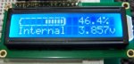
It required coding some more advanced division and multiplication code which should be useful when hitting the limmitations of PICAXE (i.e. overflows of large numbers and no floating point ability)

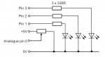
It is free for download with extensive documentation and PEBBLE based circuit here:
http://www.prlsoftware.com/pic-n-axe-batteries.aspx

This is a submission in to the project competition.
 

westaust55

Moderator
Projects "sounds" good and the screen shot photo is interesting. but . . .
the prlsoftware link just takes me into a blog for "Remote Control Programming"

Can I suggest that you upload the program code and schematic to this thread for ease of future reference for all.
 

pleitch

New Member
Hmmm.... I'm having trouble getting the Blog entry out of "Draft". I think it has something to do with the fact I'm trying to publish "now" in Australian time but the server is probably going to post it "Now" US time (i.e. tomorrow).

Here's the links to the code and the circuit.

Code and documentation

Circuit
 

pleitch

New Member
Yes - it turns out that time doesn't exists outside of the US. I set the publish date of the entry to yesterday and it happily published.

Anyway, the link has lots of photos and a bit of background.

Thanks westaust55 for pointing that out - I'll be aware of that from now on out.
 

eclectic

Moderator
Mmm.
Would it not be easier for potential viewers
if you followed Westaust55's suggestion?
Publish the program here.

Then, less hoops to jump through.

Secondly, is there a "standard" schematic available?

e
 

pleitch

New Member
Hi eclectic

I did follow Westaust55's suggestion. If you look back at post number 3 you can see two links, one is for the documentation and program and the second is for the circuit.

I'm brand spanking new to PICAXE as well as microprocessors and electronics, so I don't know what you mean by standard schematic. What's the standard and is there a free program available to allow me to do it?

In the end the project is really just a parallel LCD display with three voltage sources attached to pins, with each voltage source pulled down so the pin doesn't float. There's nothing complicated about it.

Thanks.
 

eclectic

Moderator
Not links, but posting the information here, in the thread.

Examples taken from Manual 3, just for illustration.

Code in [] [/] brackets

Code:
main: readadc 0,b1 ‘ read value on pin0 into variable b1
 if b1<75 then light1 &#8216; if b1 is less than 75 then light 1
 if b1<175 then light2 &#8216; if b1 is less than 175 then light 2
 goto light3 &#8216; if b1 is greater than 175 then light 3
 
light1: high 1 &#8216; switch on LED 1
 low 2 &#8216; switch off LED 2
 low 3 &#8216; switch off LED 3
goto main &#8216; loop
light2: low 1 &#8216; switch off LED 1
 high 2 &#8216; switch on LED 2
 low 3 &#8216; switch off LED 3
goto main &#8216; loop
light3: low 1 &#8216; switch off LED 1
 low 2 &#8216; switch off LED 2
 high 3 &#8216; switch on LED 3
goto main &#8216; loop
And diagrams as jpg files

Alternatively, upload as a pdf file.

e
 

Attachments

pleitch

New Member
Okay - I see what you mean. I can do the code thing, but how do I generate the diagram as JPG? Is there some freeware software that generates it?
 
Top