Pic 18x 'freezes'

djmikeys

New Member
I am using a pic18x with a sound sensor (mic and amp) to control both the brightness of leds as the noise increases as well as turning on 4 water pumps as the noise level increase. When I run the code for both the leds and the pumps seperetly it seems to run OK but when I combine the codes together the pic just seems to 'freeze' - it just stops with the leds and pumps staying on the same setting no matter what the noise level is. I have tried re-arranging the order of my code but I cant seem to get it to run smoothly, it seems to work OK in the simulator. Here is my code:

main:

readadc 2,b1
debug b1


if b1 =>101 then goto on1
if b1=< 100 then goto off1

on1:
w0 = b1-100
pwmout 3,255,w0
goto pumps

off1:
pwmout 3,255,0
goto pumps

pumps:

readadc 2,b1


if b1 =<110 then goto pumpoff
if b1 =>111 and b1=<130 then goto pump1
if b1 =>131 and b1=<160 then goto pump2
if b1 =>161 and b1=<190 then goto pump3
if b1 =>191 then goto pump4

pump1:
high 0
low 1
low 2
low 4
goto main

pump2:
high 0
high 1
low 2
low 4
goto main

pump3:
high 0
high 1
high 2
low 4
goto main

pump4:
high 0
high 1
high 2
high 4
goto main

pumpoff:
low 0
low 1
low 2
low 4
goto main

____________________________________________________


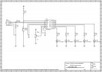
Any suggestions on why it seems to freeze? I could post a circuit diagram if its useful, but as far as I am aware it is just the code that is the issue.
Any help would be very welcome.
 

eclectic

Moderator
First thoughts.

on1:
w0 = b1-100
pwmout 3,255,w0
goto pumps

The program will get confused.
w0 = b1 and b0

Perhaps try w1 = b1 - 100

Secondly. What happens when b1 =

100, or 110, or 130, or 160, or 190?

e.
 

BrendanP

Senior Member
Hardware issue?

Try 100n and 10n ceramic decoupling caps on the power supply pins and a 10n on the reset pin.
 

djmikeys

New Member
First thoughts.

on1:
w0 = b1-100
pwmout 3,255,w0
goto pumps

The program will get confused.
w0 = b1 and b0

Perhaps try w1 = b1 - 100

Secondly. What happens when b1 =

100, or 110, or 130, or 160, or 190?

e.
I changed w0 to w1, it doesnt seem to make a difference. When B1 equals these increments more and more pumps are turned on.
 

BCJKiwi

Senior Member
Try 2 things;

1. remove the debug for the running code. You could replace it with;
sertxd ("b1 = ",#b1,cr,lf)
if you still want to see what b1 is.

2. you don't actually need to do the readadc a second time since the w0 has been changed to w1. This would also remove any slight possibilty of the LEDs and the pumps getting out of sync.
 

moxhamj

New Member
I had a similar problem recently on a slower PC. The debug data was coming back too fast for the computer. Try putting pause 1000 after the debug. Both the debug and pause can be removed in the final code.
 

djmikeys

New Member
I have tried everyones suggestions apart form BrendanP's Capacitor solution, which I will have to try tomorrow when I can get some capacitors. the problem still remains...........
 

premelec

Senior Member
I'm suspecting transient glitches... try disconnecting loads being controlled if the capacitors don't help and see if it all runs ok - you need to isolate the PICAXE from the load switching transients... It takes only a small spike of voltage to disorient the PICAXE when it hits the wrong pin at the wrong time... or is that the Right pin?
 

moxhamj

New Member
Good point premelec. I have found picaxes will reset if you switch mains voltages at 5A or more within 20cm of the picaxe, even if the picaxe is not doing the switching. Switching power devices like pumps can be tricky. I have resorted to using a picaxe to switch a transistor, then take two wires 50cm away to to switch a relay, then take the relay wires a few metres away to switch a contactor to turn a pump on. Even then, interference would get back and the transistor wires needed RF suppression (one of those ferrite things that are on all computer monitor leads). The layout is critical and it isn't easy to set up. Think of every wire going to the picaxe as an antenna picking up interference which can reset the chip. So you might have to put the picaxe in a metal box, and every wire that goes in or out of that box goes through an inductor eg a toroid with 1mm wire 100mH or so. These are pretty standard for suppression on mains leads. How big are the pumps and what is their voltage and current?

Another thought - have you actually got any pumps etc connected, or is it freezing just running the code? If the latter, then reduce the code to eliminate the problem. Start putting in debugs everywhere. Start commenting out subroutines etc. There would be a lot of efficiencies you could add to the code as well - select case structure, if then/else and using pins for output statements. The whole program could be shrunk to less than half its size. But maybe leave that for the moment until we can get some simple things working. Eg just turning a pump on and off every few seconds and see if that will reset the picaxe.
 
Last edited:

djmikeys

New Member
Dr Acula:
The code apperars to be freezing and also being 'unpredicable' with no pumps attached. I am simply just using Leds on each of the 'pump' Pins of the Pic 18x.
When I split the code in half it runs fine (use the sensor to control the brightness of the Leds and, secondly, use the sensor to control the 'pumps'(leds)). It is just when I combine the 2 parts together the Pic18x get confused

I have tried using capacitors both across the pic power supply and the reset pin and still no success........
 

BCJKiwi

Senior Member
Perhaps the two working sub programs could be posted just in case it throws some light on the combined program problem.
 

moxhamj

New Member
Agree, can you pls post. There is still that line that could send an out of range value to pwmout. Does anyone know if sending 65532 to pwmout would cause it to hang?
 

djmikeys

New Member
Ok, here are the two codes:
----------------------------

main:

readadc 2,b1
debug b1

if b1 =<110 then goto pumpoff
if b1 =>111 and b1=<130 then goto pump1
if b1 =>131 and b1=<160 then goto pump2
if b1 =>161 and b1=<190 then goto pump3
if b1 =>191 then goto pump4

pump1:
high 0
low 1
low 2
low 4
goto main

pump2:
high 0
high 1
low 2
low 4
goto main

pump3:
high 0
high 1
high 2
low 4
goto main

pump4:
high 0
high 1
high 2
high 4
goto main

pumpoff:
low 0
low 1
low 2
low 4
goto main
-------------------------------------------------------------
and the second code:
-------------------------------------------------------------

main:

readadc 2,b1
debug b1

if b1 =>101 then goto on1
if b1=< 100 then goto off1

on1:
w1 = b1-100
pwmout 3,255,w1
goto main

off1:
pwmout 3,255,0
goto main
 

BCJKiwi

Senior Member
OK thanks,

1. When I tried the led code in the simulator it failed as I had been using a different chip - Recommend that you put a #PICAXE 18X at the top of the program (but lack of this should not affect a program running in the actual hardware)
2. The pwmout 3,255,b1 does not generate an error in the simulator but is out of range for the wizard.
If you try the wizard you will find the minimum frequency is 4000 which gives the highest value for the period of 249. Higher frequencies result in lower period values so 249 is as high as you can go (I know the manual says 0-255 but I've always used the wizard.
Suggest the 255 is changed to say 245.
3. The third really weird thing is that in the simulator, the moment b1 gets a value (any value) output 2 goes high. This should not happen and I don't have an answer for that and I don't have an 18X to test - it may be a simulator issue.
I'm testing this by rem-ing out the readadc and debug lines and putting in a let b1 = xxx to give the simulator something to work with.

So can you change the pwm settings and see if that fixes the problem.
 
Last edited:

Dippy

Moderator
Some of the code is a bit redundant isn't it?

if b1 =<110 then goto pumpoff
if b1 =>111 and b1=<130 then goto pump1
if b1 =>131 and b1=<160 then goto pump2
if b1 =>161 and b1=<190 then goto pump3
if b1 =>191 then goto pump4

couldbe:
if b1 =<110 then goto pumpoff
if b1 =<130 then goto pump1
if b1 <=160 then goto pump2
if b1 =<190 then goto pump3
Goto pump4

Though there are neater ways of doing that.
 

djmikeys

New Member
Cheers Dippy, neatens things up a bit.

I tried your suggestion BCJKiwi, after changing the pwm to 245 there was no difference. I have been experimenting with the circuit this morning and found that when you disconnect the LEDs that change brightness then the other 4 pumps/leds work perfectly well, it is only when you reconnect the other LEDs that the Pic18x starts to have issues, strange. This is also the case when you run the full code but only connect the LEDs that change brightness, but when you connect the other LEDs/pumps the Pic freezes again.

Does this not suggest that the problems lie within the circuit rather than the code???

I will try and draw up a diagram of what I am using this afternoon.
 

djmikeys

New Member
Heres my circuit. Remember the 4 Leds that are coming out of the Pic18x are representing the 4 pumps. When I intergrate the pumps I will run them through the same ULN2004A as the other LEDs.
 

Attachments

djmikeys

New Member
Sorry, I forgot to add the Potentiometer that I am using temporarly to make it easier to test the circuit. I have the sound sensor made up and it seems to work fine. I am using the sound detection circuit described here: http://www.rev-ed.co.uk/docs/picaxe_sound.pdf I use a seperate voltage regulator to power this circuit as it seems to reduce electrical noise.
 

Attachments

hippy

Ex-Staff (retired)
I have been experimenting with the circuit this morning and found that when you disconnect the LEDs that change brightness then the other 4 pumps/leds work perfectly well, it is only when you reconnect the other LEDs that the Pic18x starts to have issues, strange.
There doesn't seem to be any current limiting resistors on the LED's so that could do it. Turn the LED's on, draw huge amounts of current and the PICAXE collapses into a heap or disappears in a puff of smoke.
 

djmikeys

New Member
Cheers Dippy,
I have put some 470R resistors on each of the 4 LEDs and it seems to do exactly the same, is it worth putting something to limit the current on the LED driver, it produces 1000mA.
 

eclectic

Moderator
Mshorter.

I've just used a circuit, based on a CHI030 board.
The board has two 10k potentiometers hard wired onto adc 0 and 1.
It also has 8 led/resistors hardwired to outputs 0-7.

I've made changes to your original program based on earlier suggestions and ONE other;
I've increased the value of w1 to make led3 more visible on my board.

Program
Code:
 main:

readadc 0,b1
sertxd (#b1," ")

if b1=< 100 then goto off1

on1:
w1 = b1 * 2 '********
pwmout 3,255,w1
goto pumps

off1:
pwmout 3,255,0

pumps:

if b1 =<110 then goto pumpoff
if b1 =<130 then goto pump1
if b1 =<160 then goto pump2
if b1 =<190 then goto pump3
if b1 =>191 then goto pump4

pump1:
pins =%00000001
goto main

pump2:
pins =%00000011
goto main

pump3:
pins =%00000111
goto main

pump4:
pins =%00010111
goto main

pumpoff:
pins = %0000000
goto main
I then tried using readadc on input 0, then input 1

In both cases, everything worked perfectly; the four &#8220;pump&#8221; LEDs lit in sequence and the PWM LED changed brightness.

e.
 

Mycroft2152

Senior Member
Some thoughts....

Minimize your circuit to see if the Piacaxe portion works.

Remove the LEd Driver from the circuit and try it.

Remove the ULN2004 an replace eith a LED/resistor and try it.

Add capacitors to both sides of the 7805.

Post a link to the LED Driver data sheet. NKD 1000 comes up empty in a google search.

Myc
 
Last edited:

djmikeys

New Member
I tried your code eclectic but it still seems to stall......

I was just tinkering there and turned the supply voltage down to 6V rather than 7.5V. This seems to of fixed the 'freezing' of the Pic18x. Success!!!
Does anyone know why this might be?

Now lies the challenge of replacing the 4 LEDs for water pumps and the potentiometer with the 'noise sensor'. I'll keep you posted..........

Thanks for all your help.
 

eclectic

Moderator
mshorter

OK, can you now say exactly WHAT works please?

Which code?

Which circuit?

And is the 6v the INPUT voltage to the 7805 ?
6v IN doesn't sound right for 5v OUT.
What IS your power supply? (add)

Could you substitute a 4.5v battery supply and have another check?

e.
 
Last edited:

BCJKiwi

Senior Member
Another program suggestion;

Code:
#picaxe 18X
 
main:
'Sound
readadc 2,b1
'sertxd ("Sound (b1) - ",#b1,cr,lf)
 
'LEDs
readoutputs b0
If bit0 = 1 then            'Check if pump 1 is on
    b2 = b1 - 100 * 2
EndIf
 
'Pumps
select case b1
case <110                   'OFF
    pins = %00000000
    pwmout 3,255,0
 
case 110 to 130             'Pump 1
    pins = %00000001
    GoSub LedOut
 
case 131 to 160             'Pump 2
    pins = %00000011
    GoSub LedOut
 
case 161 to 190             'Pump 3
    pins = %00000111
    GoSub LedOut
 
Else                        'Pump 4 b1 >189
    pins = %00010111        'Leds pwm on pin3
    GoSub LedOut
EndSelect 
 
goto main
 
LedOut:
pwmout 3,255,b2
Return
@ E,
pins = needs bit 3 always on else pwm is turned off.
Better if pwm is moved into case statements so moved LEDs code back to the top and moved pwm into If/then/else.
 
Last edited:

maitchy

Member
Hmmm, what did the program look like when you only controlled the pumps?

also, can you try changing the top of the program to:

main:

readadc 2,b1

b3 = 0
if b3 < 100 then led

b3 = b1-100

led:
pwmout 3,255,b3

pumps:

and let me know how it goes?
 

Mycroft2152

Senior Member
For what appears to be a simple program, there seems to be something very wrong.

I created a minimum versiojn of the 18X circuit in VSM. The only difference was that I grounded all the unused inputs. See jpg below for circuit. Then used the program in BJCKiwi post #25 as the source code.

VSM immediately crashed. Even trying to step through the program, VSM crashed immediately.

I decided to take a look at the B1, B2 calculations.

Based on the calculation B2 = B1 -100 * 2 in the simulator
For
B1 = 0 to 99
B2 = 0 to 254

For
B1 = 100 to 227
B2 = 0 to 254

For
B1 = 228 to 255
B1 = 0 to 56

Then Using the PWM calculator in the Programming Editor, I
looked at the possible pwm values of pwmpout 2. 255, b2. The pwm out range was 3900 Hz and an on time of 0 to 24%.

The next step is to look at the individual sections of the basi program.

More to come.
 

Attachments

djmikeys

New Member
Iv been pretty busy so Iv not had much time to carry on, I should make progress tomorrow. I did how ever run the 4 'pump LED's through the ULN2004 and it seems to run a little smoother still.

The final code I am using is:
---------------------------------
main:

readadc 2,b1
debug b1

if b1 =>101 then goto on1
if b1=< 100 then goto off1

on1:
w1 = b1-100
pwmout 3,245,w1
goto pumps

off1:
pwmout 3,245,0
goto pumps

pumps:

if b1 =<110 then goto pumpoff
if b1 =<130 then goto pump1
if b1 <=160 then goto pump2
if b1 =<190 then goto pump3
Goto pump4

pump1:
high 0
low 1
low 2
low 4
goto main

pump2:
high 0
high 1
low 2
low 4
goto main

pump3:
high 0
high 1
high 2
low 4
goto main

pump4:
high 0
high 1
high 2
high 4
goto main

pumpoff:
low 0
low 1
low 2
low 4
goto main

-----------------------------------------------------------
 

eclectic

Moderator
mshorter

Myc mentioned the unused inputs in his posting above.

Are ALL the unused inputs grounded via 10k resistors?
It could be a vital factor.

e.
 

djmikeys

New Member
Hi,

There still seems to be what seems to be an unexplainable problem with the circuit. Sometimes times when I turn it on it works fine, I have had it running fine for up to 20mins. Sometimes when I turn it on it just goes a bit crazy, it flashes and the pumps turn on and off.
I have tried grounding each un-used input with 10k resistors as suggested but it makes no difference. Should the outputs be grounded as-well?

Any other suggestions would be greatly appreciated.......

Mike
 

BeanieBots

Moderator
Under no circumstances should you ever ground an output. It will destroy the chip.
Replace the motors with lightbulbs to eliminate them from the equation.
If you still have problems it is either a code or circuit problem.
If the problem goes away, it is motor noise which can be solved by improved wiring and/or suppression.
 

djmikeys

New Member
I have already replaced the pumps with leds and it seem to work fine. Should I put capacitors across the pumps, if so whatsort of values?

Mike
 

BeanieBots

Moderator
I have already replaced the pumps with leds and it seem to work fine. Should I put capacitors across the pumps, if so whatsort of values?

Mike

Good, valuable information.
Likely cause is either power supply drop during startup and/or motor noise.
To significantly reduce noise, place a 100nF cap between the motor terminals AND a 100nF cap between each motor input and the motor case. All three caps must be as close as possible to the motor as possible. ie mounted on the motor itself keeping the capacitor leads as short as possible.
Make sure your PICAXE is well decoupled with 10uF+100nF.
If possible, get a 'scope on the power supply and see if it dips during startup.
Make sure the PICAXE 0v and motor power 0v do not share the same power cable/track.
 

djmikeys

New Member
Hi Beaniebots, The 'motors' I am actually using are water pumps and are incased in pastic with cables running out of them, this makes it hard to get the capacitors as close as possible. They might have to be where the cables leave the circuit, this is better than nothing right?

What do you mean by the Pic being decoupled by 10uF+100nF capacitors, is this just across the 5V to the Pic?

Mike
 

BeanieBots

Moderator
I've just re-read the earlier parts of this thread.
You've not answered a few key points about your power supply.
Turning down to 6v improving things sort of suggests that it is a power problem. The lower voltage would produce much lower noise from the motors.
It could also be that your regulator is not working properly (eg missing the ground connection) and the PICAXE is now powered at the correct voltage.
7.2v into a 5v regulator is unlikely to produce a 5v supply unless it is a low-dropout regulator.

What and where to put the caps has already been stated.
You should have 100nF both sides of the regulator and 10uF on the PICAXE side. Also put 100nF close to the PICAXE power pins.

The tricky part is how to advise further immunity on the input to the regulator. Normally, in such a circuit I would suggets a series diode and/or resistor on the input with about 470uF on the regulator input. However, I don't think you have enough headroom as it is and any series components would only make things worse unless it really is a low drop-out one.

Perhaps for now, power the PICAXE from 3 X 1.5v batteries. That would eliminate any power rail drop problems.
Double check your reset and serin connections. Your symptoms are also in keeping with a problem in this area.

If you cannot get to the motors it is hard to know what to suggest. Fitting caps any old where in a circuit can make things worse. Try all the other suggestions first. If it really can be shown that it is motor noise at the root of the problem, then you have no choice and will have to break into the casing to get close to the motor. Fitting a cap close to the drive rather than motor MIGHT help but if the noise problem is mainly air borne it WILL make things worse. In reality it is often a combination of conducted and air-borne so the outcome is unpredictable and may well vary with different cap values.
Ferrite beads on the motor might also help.

Take a good slow methodical approach to all the suggestions which have been made throughout the thread so that you be confident about what is really causing the problem. Then you can home in and fix it. Until it is identified for certain, we can only guess.
 
Top