PE 5.3.5 Axe401 Simulation

BillyGreen1973

Senior Member
Today I updated to 5.3.5 to try the axe401 simulation.
I used the code sample given in the axe401.pdf i.e.

Code:
#picaxe 28x2
#sim shield
do
high S.13
pause 1000
low S.13
pause 1000
loop
It runs fine, however when I tried to run the same code without the '#Sim Shield' directive, and changing the pin number S.13 to c.3, it still simulated as the shield base.
So I then tried changing the #picaxe directive to 18m2, this runs fine. I chnged it back to #picaxe 28x2 (#sim shield line still not there) it simuates as the shield base again.
I tried 40x2 as the #picaxe directive and it still simulates as the shield base.

If you restart the PE and run the code again without the #Sim Shield directive, everything works fine, in that it simulates a 28x2 correctly.
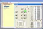
See images attached
 

Attachments

Last edited:

westaust55

Moderator
in the AXE401 datasheet, the new PE Simulation directive
#sim shield​
is mentioned :)

in the new V7.4 (Mar 2011) Manual 2 (and in the AXE401 section in manual 1 - also now at V7.4) neither
#sim shield, nor
#sim none​
seem to get a mention.
 

Technical

Technical Support
Staff member
All simulation panels are controlled by the

Simulate > Simulation Panels > Product Sims menu

#sim axe101, shield, none etc. etc.

are just shortcuts for this menu
 

centrex

Senior Member
Not quite on the same subject but still for the AXE401.
I have just assembled mine from the kit, when powered up without the 28x2 in the socket checking that all the voltages were correct I noticed..
The power led came on full bright OK but the led connected to C.3 or S.13 glowed but not full bright.

Installing the 28x2 and running the test program all is ok.

Just a little puzzled anyone else noticed this.
Centrex
 

westaust55

Moderator
Based on the datasheet schematic I would believe the LED should not illuminate at all without the PICAXE installed and programmed to do so.

What happens if the PICAXE and the H4 jumper are both removed ? :confused::confused:

I would be checking for a high resistance joint in the form of a solder bridge that would cause the LED to illuminate at a low level/intensity.
 

BillyGreen1973

Senior Member
Have you installed the 4k7 ups for the I2C socket?
If so, this is whats causing the c.3 led to light.
S.13 os also an I2C line, so pulling it up provides power through the 4k7 to the led. Removing the H4 jumper will turn off the led. To use the I2C you need to remove the H4 jumper anyway.


In my axe401 I used the C.3 led to check all was constructed correctly, then romoved the H4 jumper permanantly, to allow use of I2C. I have more use for I2C than a flashing led!
 
Last edited:

westaust55

Moderator
Ah yes, BG1973 is correct.

Looking again at the datasheet, R5 and R6 are the i2c bus pull up resistors.
They are shown on the diagram for the IC2 on page 10.
 

westaust55

Moderator
A way around the i2c pull up resistor issue is to do the same as I have done on my AXE022 boards.

I installed header sockets on the board and then have the two resistors soldered across some header pin segments so that they can easily be removed is some other device is conencted to the i2c bus which happens to have pull up resistors fitted by default - such as the AXE033 LCD module.
 

hippy

Ex-Staff (retired)
Other options may include pull-ups connected to PICAXE pins which can be set high to pull-up the I2C bus or to use the internal weak pull-ups.

In using the Shield Base for non-I2C projects with an I2C Eeprom fitted there will always be potential for some issues should the Eeprom inadvertently be activated and pull one of the I2C bus lines low and it would probably be best to remove the Eeprom and perhaps the pull-ups in some instances, or use a different Shield Base altogether.

It's always difficult to decide what any project board should support, and there's rarely any perfect solution which allows 'everything' but doesn't require some compromise. In this case, adding optional support for I2C Eeprom saves the user from having to add a Shield to support data logging, allows a single board datalogger to be constructed using a Shield Base, but for those who take this option they have to accept that this does have consequences. That however seems a better proposition than not providing the ability to use such Eeprom on-board.
 
Top