Path lighting circuit

knight

Member
Okay i need a sanity check of my circuit.

I'm building lights for the path at home as its an old brick path that roots have come and damaged and at night it can pose a trip hazard.

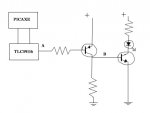
Anyway i'm using a TLC59116 LED controller, its a constant current PWM I2C LED controller which i'm using to control a common anode LED RGB light from The Big Clive. The LED controller pulls the pin in question low to turn the LED on. This means i can't simply use a normal transistor to turn the LEDs on.

I've attached a circuit diagram. When I turn the led on, point A should go low, which should pull point B high thus turning the LED on.

Will this work or do i not need the second transistor?

EDIT:
The datasheets are as follows:
TLC59116
LED light
 

Attachments

Last edited:

westaust55

Moderator
The concept as you describe with the transistors is correct and needed because the TLC59116 is a current sinking IC.

But before we go further, can I ask why are you using the TLC59116 and then following that with transistors?

The TLC59116 is rated for Constant Output Current Range: 5 mA to 120 mA
Also suited for RGB LED's

Can you enlighten us further on
  • the concepts,
  • how many LED's,
  • are the LED's RGB or just white,
  • are you looking for variable brightnes hence the TLC59116,
  • what is the proposed LED current,
  • which transistors are proposed - has impact or resistor selection,
  • etc, etc.

There may be better ways to achieve your goals but the information is too limited to give any advice.
 

techElder

Well-known member
Why don't you just put the LED in the PNP path to ground? The NPN is superfluous.

PS. Around here you can buy those things for less than $5 each. Also you can get the innards on the cheap and make a rechargeable lamp in your own chassis/box.
 
Last edited:

knight

Member
Okay, sorry Westaust, let me see if i can enlighten you.

The system is designed to be modular, a picaxe based controller in the house and 1 or more light modules outside.

The light modules consist of a picaxe, a 59116, 8 dip switches to set the address and the LEDs themselves. The LEDs are single colour superflux LEDs from phenoptix (linked below) mounted together so as to enable RGB mixing.

The master controller sends out commands via serial to enable different effects as required, the light modules react based on the addressed light matching the set address or a broadcast address. The picaxe then sends the command to the 59116 which activates and so on.

I am looking for variable brightness to enable the full spectrum of colours as well as effects such as cross fades and fade up/fade to black, hence the choice to use the 59116.

Each of the panels i'm planning on using in the primary lights (previously linked here contain 9 LEDs, 3 red, 3 green and 3 Blue.

I hadn't decided to go with the transistors or not, i was simply considering my options and just confirming i got the circuit at least close to right. However on reflection I believe i will need the transistors as the link says that the modules should be run at 12 volts.
Additionally there is a second module, larger than the one i'm using at the minute that i'm also considering implementing, it contains a total of 54 LEDs, 18 of each colour.

Anyway linked data for the LEDs as requested:
Red
Green
Blue

Again sorry, I know the first question that seems to get asked is always for more information which i tried to pre-empt, ovbiously failing badly :p

Thanks for the help.
 

eclectic

Moderator
snipped
Additionally there is a second module, larger than the one i'm using at the minute that i'm also considering implementing, it contains a total of 54 LEDs, 18 of each colour.
I presume both of the boards are from Big Clive.
(I own both myself)

What resistors did you use, or
even better:
What's the maximum current draw for each channel?

e
 

westaust55

Moderator
I hadn't decided to go with the transistors or not, i was simply considering my options and just confirming i got the circuit at least close to right. However on reflection I believe i will need the transistors as the link says that the modules should be run at 12 volts.
The TLC59116 LED controller is low side switching and only sinks current to ground. From the datasheet, the outputs are rated to handle:
Maximum Output Voltage: 17 V
so the IC is capable of handling the voltage you intend using to power the LEDs.
Therefore the matter becomes one of the total/summation of the current and power dissipation capabilities of the TLC59116. Have you checks those details in the datasheet.
 

knight

Member
Well don't i feel silly.

Rule number 1: RTFM! (or more correctly RTFD)
Rule number 2: Provide details, datasheets, circuit diagrams and photos.

Anyway, did some tests this evening using the small module, as i havn't built the larger module yet (and its not important as its only a secondary part of the system), the results were as follows:

For a supply voltage of 12.05V:

Red - 31.9mA (Voltage across the LEDs 11.66V)
Green - 26.5mA (Voltage across the LEDs 11.76V)
Blue - 24.8mA (Voltage across the LEDs 11.76V)

The total power dissipation max for the chip is 1336mW, so even working on a worst case voltage drop through the chip, running only 3 channels, i should never get even close the total dissipation.

@Eclectic, I have looked at your thread, that was what originally put me onto the boards, and i'm planning to use the large panel in a manner similar to you, to cover an area where i can't put small lights (as we drive cars over the area :p)

Thanks for all the help, I'll post a finished project once its all done.
 
Top