Parallax line follower Kit #28034 + Picaxe 28X on AXE020...newby.

Hi,
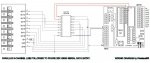
I'm building my 1st Line Follower robot, the board I'm using is a Picaxe 28A + Line follower kit from Parallax #28034.
Infrared Line following kit: http://www.parallax.com/Portals/0/Downloads/docs/prod/sens/28034-InfraredLineFollower-v1.0.pdf

The Line follower kit power input = 3.4V, all pins 0~7 = 2.9V, when the sensor is covered up the Voltage reads 0V.
I need a very simple code just to test the line following kit sensor and the stepper motor driver + Motor.

cw:
pulsout B.1,150 ' send a 1.50ms pulse out of pin B.1
high 1
goto cw ; loop back to start

ccw:
pulsout B.1,150 ' send a 1.50ms pulse out of pin B.1
high 0
goto ccw ; loop back to start

I want the motor to turn cw when sensor 0 is activated, and turn ccw when sensor 1 is activated, any help would be great :)..
 
Last edited by a moderator:

westaust55

Moderator
Can you clarify a few things first:
1 by sensor 0 and sensor 1 do you mean you have 1 line follower kit and using just two adjacent IR receivers, or do you have two line followers (one to the left and one to the right)

2. You say you have a 28A (a very early PICAXE chip) but then are using the Port.pin method for IO pin addressing as recommended for the very latest M2 and X2 parts. Please confirm it is a 28A. Good to know for sure as the "A" series have less memory and do not have the full range of commands available on the more recent chips.

3. what board are you using as the basis of your line following robot. A Rev Ed kit or a board from other sources?

4. Please provide a schematic diagram showing how / to which pin the line follower kit(s) and motors are connected.

5. If using a single Parallax kit, is there any reason why only using two (out of 8) of the IR receiver signals. If this is due to available PICAXE input pins I can advise an easy way to get all 8 signals into the PICAXE.with 1 input and 2 outputs using a 74HC165 which can parallel load 8 bits of data and serially shift that into the PICAXE (into a byte variable).

With sufficient information we can give you much more specific code to your project.
 
Last edited:
Can you clarify a few things first:
1 by sensor 0 and sensor 1 do you mean you have 1 line follower kit and using just two adjacent IR receivers, or do you have two line followers (one to the left and one to the right)

2. You say you have a 28A (a very early PICAXE chip) but then are using the Port.pin method for IO pin addressing as recommended for the very latest M2 and X2 parts. Please confirm it is a 28A. Good to know for sure as the "A" series have less memory and do not have the full range of commands available on the more recent chips.

3. what board are you using as the basis of your line following robot. A Rev Ed kit or a board from other sources?

4. Please provide a schematic diagram showing how / to which pin the line follower kit(s) and motors are connected.

5. If using a single Parallax kit, is there any reason why only using two (out of 8) of the IR receiver signals. If this is due to available PICAXE input pins I can advise an easy way to get all 8 signals into the PICAXE.with 1 input and 2 outputs using a 74HC165 which can parallel load 8 bits of data and serially shift that into the PICAXE (into a byte variable).

With sufficient information we can give you much more specific code to your project.
Westaust55,
1. Yes 1 line follower kit and using 2 adjacent IR receivers for test.
2. I confirm it again, it is the 28x 40X installed not the 28A (I hace 2 chips). http://i1220.photobucket.com/albums/dd459/happytriger2000/Picaxe/Firmware.jpg
3. http://i1220.photobucket.com/albums/dd459/happytriger2000/Picaxe/DSC04658.jpg. I also have 2 Picaxe 18 boards.
4. http://i1220.photobucket.com/albums/dd459/happytriger2000/Picaxe/Illustration.jpg
5. I have seen some example code for Line follower kits and I don't understand the meaning of the code, so that's why I asked for a simple program code to start with.
 

inglewoodpete

Senior Member
I had a look at the datasheet for the line follower add-on kit. It is just that: an add-on for a Boe-Bot or Stingray robot chassis.

You mention that your robot uses stepper motors. I have to admit I haven't seen stepper motors that look like those in the photos in the line follower datasheet, but I have led a sheltered life!

Stepper motors are not the simplest things to drive. Do you know how these are wired?
Inglewoodplete,
for stepper motor driver you need to send a pulse to the Puls - and a high or low to Dir -, Pilse + & Dir + are shorted and supplied by a +5v.

Here is a videoof the motor running + Picaxe 28X40X: http://youtu.be/qjxEImz3yBM
 

westaust55

Moderator
The AXE121 datasheet is available here: http://www.picaxe.com/docs/axe121.pdf
This was the now obsolete AXE120 (see here: http://www.picaxe.com/Datasheet-List near bottom of page)

From your photo which shows a PIC 16F873A you have a 28X chip and an AXE020 project board (See: http://www.picaxe.com/docs/axe020.pdf).

From the You-Tube video you have a stepper motor with some external "box"/module as an interface to drive the motor.


The Parallax line follower board is seemingly relatively easy to use. If you have already purchased this board,
and have available 1 input and 2 outputs I would recommend adding the already mentioned 74HC165 chip as an interface and then using all 8 channels rather than just 2.
However in the absence of a full schematic for your project showing also the motor connections.
The 8 channel board gives you the option to vary the degree of turning relative to the distance the line is away from the line being followed.

Let us know how you wish to proceed and folks here will try and help. A full schematic or at least a detailed list of what devices are connected to what PICAXE pins will help.
It is best, as I am sure you understand, to try and get the fundamentals sorted before folks start offereing solutions.

Should I amend the thread title to reflect that the PICAXE is a 28X (not a 28A)?
Westaust55,
Yes I do have the parallax Line Follower kit and will get the 74HC165 asap.
Once everything is ready I will create a schematic in autocad.

Yes please amend the title,

thanks,
 

westaust55

Moderator
Attached as promised is a Wiring/hook-up Diagram based upon using
  • input0 for the data-in from the Line Follower module
  • output7 for the Loading the LF data to the shift register
  • output6 for the clock pulses to shift the data from the shift register to the PICAXE data-in pin

Below is some code that will bring the 8 bits/channels of data from the Line Follower into the PICAXE into byte variable b0.
The data is then displayed in the PICAXE Programming Editor Terminal Window (opened using the [F8] key if not already open)

Code:
#PICAXE 28X
#NO_DATA
; Assumptions;
;1. The line follower Enable pin is pulled high via resistor - so the LF does not change to low power mode
;

;===== Define Input pins
SYMBOL LF_SDat	= pin0	; Input pin for Serial Data in from Line follower via Shift Reg

;===== Define Output pins
SYMBOL LF_Clk	= 6	; Output pin for Clocking data in from Line Follower via Shift Reg
SYMBOL LF_Load	= 7	; Ouput pin for Parallel loading of LF data into Shift Register

;===== Define variable alias names
SYMBOL LF_Data	= b0	; Variable used to hold the data clocked in from the Line Follower
SYMBOL Counter	= b5	; Used as index for FOR...NEXT loops

;Initialise the PICAXE
Init:
	HIGH LF_Load ; set the Shift Register Parallel Load signal high for idle state
	
; Main Program Loop
Main:
	DO
		GOSUB LF_DATA_In ; Enter the present status of the Parallax 8-channel line follower
		SERTXD ("Ch7 to Ch0 = %", #bit7, #bit6, #bit5, #bit4, #bit3,#bit2, #bit1, #bit0, cr, lf)
		PAUSE 1000 ; delay to control input data rate so one can see the data coming in from Line Follower
	LOOP

;===== [ SUBROUTINES ] ==========

;; ***** Shiftin serial data with MSB first, Data Pre-Clock *****
LF_DATA_In:

	LF_Data = 0			; clear the LF data variable ready to accept a new reading
	PULSOUT LF_Load, 1 	; Toggles the shift register line to parallel load LF data to shift register 
	
	FOR Counter = 0 TO 7 	; shift in 8 bits of data from Line FOllwer via shift register
		LF_Data = LF_Data * 2	; shift data already in variable 1 bit left towards the MSB 
		IF LF_SDat = 0 THEN skipMSBPre
		LF_Data = LF_Data + 1	; set the LSB if serial data line = 1
skipMSBPre:
		PULSOUT LF_Clk, 1	; Pulse the shift register clock ready to load in next data bit
	NEXT counter		; repeat until 8 bit of data representing the 8 channels of the LF are received
	RETURN
I suggest that you prove this section of code before trying to add motor control.
When the program is running, if you move a piece of white card with a thick black line (width maybe as wide as distance between two Line Follower channels/sensors) across face of the the Line Follower then you should see the bit/channel in the displayed data move as well.

I can provide some further code (later) in line with the Line Follower datasheet to control the degree of turning as the line is further from the centre of the line follower sensors.

Once this part is running you will need to give folks here more informaiton about the stepper motors and controller as seen in your video or work out for yourself how the adjust the stepper motors speed. Otherwise it is unclear to myself at least exactly how what values are needed to adjust the degree of turning/steering.
 

Attachments

Thanks Westaust55!!.

I bought some MM74HC165N today: http://www.datasheetcatalog.org/datasheet2/b/0dwxh6hcgp3suhs9xgadj5x7ag3y.pdf

http://i1220.photobucket.com/albums/dd459/happytriger2000/Picaxe/DSC04660.jpg

http://i1220.photobucket.com/albums/dd459/happytriger2000/Picaxe/DSC04661.jpg

Ok, program went through ok.

About the Driver, it is very much the same as Easy driver but it drives a larger Motor.
The driver has 8 microstep mode, curently I set it to 200 pulse/rev.

Using Pulsout command:

pulsout B.1,1 ' send a 1.50ms pulse out of pin B.1 (this is the maximun speed)

high 6

Changing the speed by changing the ms value..e.g. 1~1000, 1 is the max ~ 65535 min.

http://youtu.be/0PaTRASGKY8

For a even better result use ramping, like those in cnc machines, but I have no idea how to do that, sine wave prob.?

PWM is also an alternative way.
 

westaust55

Moderator
Now I am not a robot builder but here is some code that uses the byte received serial in from the Line Follower Kit and sets the motor speeds depending upon the degree of variation of the line from the centre of the Line Follower sensors.
If you need more help I am sure others can step in here as well to provide alternate/better code but this should see two motors running and change speed are degree of turning relative to deviation from the line being followed.

Code:
#PICAXE 28X
#NO_DATA
; Assumptions;
;1. The line follower Enable pin is pulled high via resistor - so the LF does not change to low power mode
;

;===== Define Input pins
SYMBOL LF_SDat	= pin0	; Input pin for Serial Data in from Line follower via Shift Reg

;===== Define Output pins
SYMBOL LF_Load	= 7	; Ouput pin for Parallel loading of LF data into Shift Register
SYMBOL LF_Clk	= 6	; Output pin for Clocking data in from Line Follower via Shift Reg

SYMBOL MtrLeftCtrl = 5  ; Output for the left motor control pulses 
SYMBOL MtrRghtCtrl = 4  ; Output for the right Motor control pulses
SYMBOL DirectnCtrl = 1	; output to set motor direction - ultimately may need separate for each motor


;===== Define variable alias names
SYMBOL LF_Data	= b0	; Variable used to hold the data clocked in from the Line Follower
SYMBOL Counter	= b5	; Used as index for FOR...NEXT loops

SYMBOL MtrLeftSpd = w3	; w3 = b7:b6
SYMBOL MtrRghtSpd = w4	; w4 = b9:b8
SYMBOL Direction = b10


;===== Define constants for motor speed for turns
SYMBOL V_Slow	= 1000
SYMBOL Slower	= 875
SYMBOL Slow		= 750
SYMBOL Mod_Slow	= 625
SYMBOL Moderate	= 500
SYMBOL Mod_Fast	= 375
SYMBOL Fast		= 250
SYMBOL Faster	= 125
SYMBOL V_Fast	= 1

SYMBOL Fwd_Dir = 1
SYMBOL Rev_Dir = 0

;Initialise the PICAXE
Init:
	HIGH LF_Load ; set the Shift Register Parallel Load signal high for idle state
	Direction = Fwd_Dir
	
; Main Program Loop
Main:
	DO
		GOSUB LF_DATA_In ; Enter the present status of the Parallax 8-channel line follower
		GOSUB Ident_Deviation
		GOSUB Set_Motors
		PAUSE 200
	LOOP

;===== [ SUBROUTINES ] ==========

; ***** Shiftin serial data with MSB first, Data Pre-Clock *****
LF_DATA_In:

	LF_Data = 0			; clear the LF data variable ready to accept a new reading
	PULSOUT LF_Load, 1 	; Toggles the shift register line to parallel load LF data to shift register 
	
	FOR Counter = 0 TO 7 	; shift in 8 bits of data from Line FOllwer via shift register
		LF_Data = LF_Data * 2	; shift data already in variable 1 bit left towards the MSB 
		IF LF_SDat = 0 THEN skipMSBPre
		LF_Data = LF_Data + 1	; set the LSB if serial data line = 1
skipMSBPre:
		PULSOUT LF_Clk, 1	; Pulse the shift register clock ready to load in next data bit
	NEXT counter		; repeat until 8 bit of data representing the 8 channels of the LF are received
	RETURN
	
;***** determine the degree of deviation/turning from the line and set motor speeds to compensate ***** 	
Ident_Deviation:
	SELECT LF_Data ' Select line follower states
		CASE %11000000, %11100000	' Pivot right
			MtrLeftSpd = V_Slow
			MtrRghtSpd = V_Fast
		CASE %01100000, %01110000	' Curve right
			MtrLeftSpd = Slower
			MtrRghtSpd = Faster
		CASE %00110000			' Slight right
			MtrLeftSpd = Slow
			MtrRghtSpd = Mod_Fast
		CASE %00111000			' Adjust right
			MtrLeftSpd = Mod_Slow
			MtrRghtSpd = Moderate
		CASE %00011000			' Straight
			MtrLeftSpd = Moderate
			MtrRghtSpd = Moderate
		CASE %00011100			' Adjust left
			MtrLeftSpd = Mod_Fast
			MtrRghtSpd = Moderate
		CASE %00001100 			' Slight left
			MtrLeftSpd = Fast
			MtrRghtSpd = Mod_Slow
		CASE %00000110, %00001110	' Curve left
			MtrLeftSpd = Faster
			MtrRghtSpd = Slower
		CASE %00000011, %00000111	' Pivot left
			MtrLeftSpd = V_Fast
			MtrRghtSpd = V_Slow
	ENDSELECT
	RETURN
	
;***** determine the degree of deviation from the line and set motor speeds to compensate *****
Set_Motors:
	IF Direction = Fwd_Dir THEN
		HIGH DirectnCtrl
	ELSE 
		LOW  DirectnCtrl
	ENDIF
	
	PULSOUT MtrLeftCtrl, MtrLeftSpd 
	PULSOUT MtrRghtCtrl, MtrRghtSpd 
	RETURN
Thanks for the code.
I'm not really good at code.
Question: Is this code suit for DC motors or stepper motors and which pins are assigned for the motors?
 
Last edited:
Ok, the motor pins are:

SYMBOL MtrLeftCtrl = 5 ; Output for the left motor control pulses
SYMBOL MtrRghtCtrl = 4 ; Output for the right Motor control pulses
SYMBOL DirectnCtrl = 1 ; output to set motor direction - ultimately may need separate for each motor
 

westaust55

Moderator
That it the advantage of using the SYMBOL statement and alias names.
Names that are meaningful and easy to restructure IO allocation & variables as needed later on without having to find every instance in a program.
 
Video:
[video=youtube_share;8DXLwJvoUJ0]http://youtu.be/8DXLwJvoUJ0[/video]

The 2 stepper motor started turning when the LF left sensor are on (led on) , and kept turning at that speed disregarding what Line follower is sensing.

Probably it would be easier to try DC motor 1st, will add a L239D chip to 28X
 

westaust55

Moderator
How wide is the line you are using for the line follower to sense.
I have used the example from the Parallax datasheet a the basis and the line needs to be around 2 to 2.5 sensors in wide so that at least 2 and sometime 3 sensors change state at any one time.
For a thinner line you will need additional CASE statements in the Ident_Deviation: subroutine to cover cases with only 1 or 2 sensors active.

Looking back at the code I wrote last night, in the Ident_Deviation: subroutine you will likely need to swap the MtrLeftSpd and MtrRghtSpd variable labels or values as I think if it is to the left it will try to go further left as written :mad:
At 1st I drew a black line on a piece of paper which then I thought is not really precise, so I bought some black tape stick on to a white plastic plate as shown here:


but the motor still stepping same as before...
 
Last edited:

westaust55

Moderator
You need to provide a little more information about how/why it is not working.
1. Confirm that the variable for the LF_Data is changing as you move the line follower slowly over the line. Try recording and advising the value for each step as different sensors are over the line.
2. Confirm that the two motor speed variables are changing as the line follower is moved over the black line

That will give folks here an idea whether the information from the line follower is being read into the PICAXE and if the code is modifying the motor speed values ( between 1 and 1000).

If this part is correct then we can look into the motor control aspect.
Keep in mind you can see the equipment - the rest of us o ly have the information you pass to us.


Also instead of starting your post with a full copy of the previous post by using the "reply with Quote" button, either just keep the pertinent sentence or use the "Reply to Thread" button at the bottom left of the thread.
 

westaust55

Moderator
Using the PULSOUT commands as done per your example in post 1 means that a pulse is only sent to the motor once per cycle of the program, so as the program becomes more involved, the “OFF” time is longer relative to the pulses and the motors run slower for a given setting/pulse duration.

By comparison, PWM functions in the background continuously and you need only change the mark to space ratio (on to off time).
I have gone back to a n earlier version of the PICAXE manual 1 and can see that the older 28X had two PWM outputs. These use – For PWM1 the connection is input pin1 (physical leg 12) and for PWM2 the connection is Input pin 2 (Physical leg 13).
For the 28X, only the PWMOUT command is available to you.

I suggest that you step back and do some trials using the PWMOUT command (See latest V7.8 PICCXE Manual 2 page 165) to control the motor speeds. You will be far better getting one section of the project going/proven at a time rather than trying to construct an entire project and then not knowing exactly which part is not corking correctly.

PWM can, via a suitable transistor (with necessary interface resistors), directly drive a DC motor.
For a stepper motor you need added circuitry such as the L293D (max continuous current = 600 mA) which may be rated too low on current for the motors in your photos or other "H" bridge controller. The controller module you have seems to handle the motor when you use the onboard pot for manual speed control.

EDIT:
Looking again at the schematic for that stepper controller you have in the video clips (schematic attached at post 14) , it seems the controller is intended to step the motor one step for each pulse.
Thus changing the pulse duration will not change the speed. Nor will changing the mark to space ratio in a PWM pulse stream.
You need to change the rate at which the pulses are sent.
For PWM this means changing the period rather than the duty cycle.
That would explain why the motor speeds do not change.
 
"For the 28X, only the PWMOUT command is available to you.
I suggest that you step back and do some trials using the PWMOUT command (See latest V7.8 PICCXE Manual 2 page 165) to control the motor speeds. You will be far better getting one section of the project going/proven at a time rather than trying to construct an entire project and then not knowing exactly which part is not corking correctly."

Yes, I realised that 28X only support PWMout, will order some 28X2 soon.

Here's the pdf of Kit179 Stpeer driver: http://www.kitsrus.com/pdf/k179.pdf
 

westaust55

Moderator
You can still control the period with the PWMOUT command on a 28X

Without checking, one likely area where you may experience difficulties when using the 28X is the minimum frequency that can be achieved. For later chips there is the PWMDIV4 and PWMDIV16 parameters for lower frequencies (pulse rates).

EDIT:
You can use the PWM wizard in the Programming Editor to find the values for different frequencies for the 28X chip (and others if/when you have a 20X2). Select a series of frequencies and then use these to determine a set of motor speeds
 
Last edited:

erco

Senior Member
Speaking of the Parallax Line Follower kit, check out the Parallax Line Follower course at their upcoming Expo in April:

 
Westaust55,

"You can use the PWM wizard in the Programming Editor to find the values for different frequencies for the 28X chip (and others if/when you have a 20X2). Select a series of frequencies and then use these to determine a set of motor speeds"

Kool wizard, I tried different value for Period and Duty cycle on output pin 1 :

pwmout pwmdiv4, 1, 124, 250 (2000Hz, 505 duty cycle)
pwmout 1, 9, 20(10000hz, duty cycle 50%)
pwmout 1,1, 1
pwmout B.1,9,20
pwmout B.1,100,500

but still no movement.

Thanks for the info. Erco.

This is what I have in mind:

Build a 4093 cicuit like the schematic in post 14, use pwm command to replace the VR/pot, and changing the period for speed up or down.

thanks
 

westaust55

Moderator
Do you have the Ground ( 0 volt) line for the PICAXE connected to the Ground (0 Volt) line for the Stepper motor controller?

All grounds for the Line Follower, 74HC165, PICAXE board, and Stepper motor controller(s) must be connected together as the reference for the signals.

Another thought as well.
Back in post 1 you mentioned 3.4V supply to the line follower module.
What voltage are you operating the PICAXE at?

The CD4093 which is at the front end of the stepper motor kit has Schmitt Trigger (ST) type inputs. The kit has an internal 5V regulated supply.
The CD4093 inputs will require at least 3.5V to register a high state. If you have been operating the PICAXE at 3.8V try using 5V.
 
Last edited:
Yes all gorund were conected together, and this is only the stpper motor test, no LF connected.
Before it was cannected to a lab type Dc PSU, http://www.lokopower.com/english/view_class_product.asp?show=2&ST_ID=1456&F_ID=1000392, and now I swap to a switching power supply 5V,-12V, +12V.


The 4093 oscilating circuit is equivalent to pwm command, so from what I said before about picaxe replace VR is not necessary.. but how to make the stepper motor run smoothly using pwm command? I got to wait till the new chip arrive to test pwm.


westaust55

Moderator
No the CD4093 oscillator is not intended as PWM, the on to off period will be relatively constant. All it does is change the frequency as the potentiometer is adjusted so that you get less pulses for slow speed and more pulses for high speed.

Try something like this:
Code:
Symbol motor = 1
for b0 = 0 to 255
  b2 = 255 - b0
  For b1 = 0 to 150 ; number of repeats at a given speed before changing speed
    High motor
    Pause 2 ; constant 2 ms pulse width
    Low motor
    Pause  b2 ; variable delay between pulses
  Next b1
Next b0
See if that when connected to the stepper driver will change the motor speed.
If not, in case a PICAXE output has failed motor the PICAXE connection to another output and change the Symbol statement to match.

If that is not working then send a clear photo so that we can check the wiring by tracing wires on the photo (so no spagetti wiring).
If a very simple code such as the above does not function in place of the 4093 IC based oscillator then there is a hardware compatability problem somewhere.
 
Last edited:
Oh I see..changing frequency...kool

Tried the code, and the motor is stepping but not veryy fast...tik tik tik... need more speed.


EDIT- sorry happytriger - meant to reply with quote and edited your post by mistake :mad: westaust55
 
Last edited by a moderator:

westaust55

Moderator
Did you let the code work right through? May take a while to slowly accelerate.

For a faster start and more rapid acceleration try:
Code:
Symbol motor = 1
for b0 = 0 to 127
  b2 = 127 - b0
  For b1 = 0 to 50 ; number of repeats at a given speed before changing speed
    High motor
    Pause 2 ; constant 2 ms pulse width
    Low motor
    Pause  b2 ; variable delay between pulses
  Next b1
Next b0
But at least it demonstrates the PICAXE can get the pulses to the stepper driver module.
 
Last edited:
Run the code and it is faster than the previous one.

modify code:

Symbol motor = 1
for b0 = 0 to 127
b2 = 1 - b0
For b1 = 0 to 65355 ; number of repeats at a given speed before changing speed
High motor
Pause 2 ; constant 2 ms pulse width
Low motor
Pause b2 ; variable delay between pulses
Next b1
Next b0

and the result was :

Ok, need to ask a newby question:
Does b1 = pin 1 and b2 = pin2?
 

westaust55

Moderator
Run the code and it is faster than the previous one.

Ok, need to ask a newby question:
Does b1 = pin 1 and b2 = pin2?
Okay, seems you are on the way . . .
Possibly now based on the information given to you, you are able to try and integrate the parts of the porgrams previously given based on varying the frequency (not specifically the PWM duty cycle) and tentatively advance your project.
You can change the values in the previous SELECT...CASE to define suitable times for motor speeds and see if motor speed changes with deviation of the line relative to the line follower kit.

for your question, No

With respect to your 28X:
b0, b1, b2 . . . . b13 are byte variables (8-bits each) capabile of holding a value from 0 to 255.
likewise, w0, w1, w2 . . . w6 are word variables (16 bits each) capable of holding a value from 0 to 65535.
Note also that there is overlap and for w0, this is also the space used by b1 and b0.
See PICAXE manual 2 page 10 for details about PICAXE variables.

For the 28X you are using, there are 8 normally inputs and 8 fixed outputs. For each 8 pins the identifier is a number from 0 to 7.
The 8 "normal" inputs can be used in a linited way as outputs.
There are also 4 nominally analog inputs that can in a limited way be used as digital inputs.
See PICAXE manual 1 for more details on the PICAXE pin usage.

So HIGH 1 will set output pin 1 to a high (approx 5V) level

As the 28X is an older (but still useable) chip the manuals gloss over it somewhat. Some pins have less functions than the 28X1.
Attached is a pinout diagram form V5.2 of the manauls (from before when I started with PICAXE) that may help you.
 

Attachments

Got my 28X2 chip, tried pwm and running ok.

In post 28 the pwmout should work ok it did not turn because I had the puls- connected to the wrong pin. Tested ok.

main:
pwmout B.0, 99, 200 ;

goto main ; loop back to start
 
Received my Axe121 line follower kit, wired up to 28X2(new chip):

[video=youtube_share;SjPmjoqFM7Y]http://youtu.be/SjPmjoqFM7Y[/video]

Code:
init: pause 10000 ' motor controller start up pause
main:
if pinC.1 = 1 then go_f ' forward
if pinC.0 = 1 then go_l ' left
if pinC.2 = 1 then go_r ' right

goto go_s ' stop as no line nearby

go_f: 

pulsout B.0,1 
low B.1
pulsout B.2,1
low B.3

goto main

go_l:

pulsout B.0,1 
high B.1
pulsout B.2,1
low B.3

goto main

go_r: 

pulsout B.0,1 
low B.1
pulsout B.2,1
high B.3

goto main

go_s:

low B.0
low B.1

low B.2
low B.3


goto main
Ok, this post supposed to be using Parallax line follower kit with Picaxe28X/x2, but find it AXE121 is much simple to play with..
 
Top