Output from 12V alternator to PicAxe ADC pin for a rev-counter can anyone help?

SAborn

Senior Member
SAborn. No I didn't try the gnd way around with the LED. When connected the positive way straight from W connection it was flickering on and off at low revs I assume from that it was AC. But I will try it and let you know.
No real need to redo the test as i think you have answered the question ... it filckers... if your rpm was higher you would not see the flicker, so hence the reverse led test as one dont know how your tests are conducted.

Working with a guess of 300 RPM low revs, and a 1:3 ratio of the pulleys (6" to 2") that would give a alternator speed of about 900 RPM, divided by 60 (sec) would give 15 Hz, and well within the optical range to see the Led flicker.

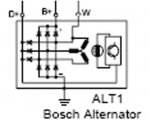
My guess its a single phase from the 3 phases that is connected to W terminal, it could be the star connection of the 3 phase, but would think its a diode gated connection to a single phase, and more than likely a DC square wave output. Then im just guessing here.
 

kando

Senior Member
Saborn.
Just to let you know that when I did the LED test to gnd it did flicker at low revs but not at higher revs.
I connected my MM to the W connection and GND and got between 7 - 7.3V on the Dc and on the AC I got between 7.6 and 8VAC.
and that was at any rev low or high.
Does this make any sense to you?

I do have a Hz selection on the MM if this is any good for anything?
 

SAborn

Senior Member
Reading the Hz with your meter will or should tell you the frequency of the pulse and it should increased/decrease with engine revs, basically your Hz is a uncalibrated RPM meter, Hz are pulses per second and Rpm ... well ... revs per minute.

If you take the Hz and divide it by the alternator pulley ratio and times it by 60 you should have your RPM.
For 1000 rpm it would be 1000 x 3 (pulley ratio) = 3000 / 60 = 50 Hz.

You will need to check your pulley ratio to workout RPM from frequency, (3 is only a guess)

Try a test with the meter between "W" and ground and see what Hz you get, some meters dont read low Hz very well.
 

SAborn

Senior Member
I dont recall if you told us the brand of alternator, but here is drawing of a bosch alternator showing "W" as connected to 1 x phase and diode gated to ground.

It might give you a better idea of how the Alternator is wired.

bosch alternator.JPG
 

rossko57

Senior Member
I connected my MM to the W connection and GND and got between 7 - 7.3V on the Dc and on the AC I got between 7.6 and 8VAC.
When making your filter/limiter/isolator, do bear in mind your meter is averaging a signal more like 15V peak.
 

fernando_g

Senior Member
When making your filter/limiter/isolator, do bear in mind your meter is averaging a signal more like 15V peak.

You should also be aware of load dumps.
This happens when the engine is running at high speed and a high current load is shed. The result is a voltage spike up to 120 volts that can last 300 msec .

The best way to eliminate that is a 2-stage limiter. The first stage, via a resistor and tranzorb/varistor, clamps it around 30 volts. Then a cascaded second stage, via a resistor and zener, clamps it to 4.7 volt.

This is a fairly common occurrence.
 
Last edited:

MikeAusP

Member
Funny innit, meself I wouldn't mess with optocouplers - there'd be precious little isolation, you have common ground and power supplies after all. . . . .
Even where there are common grounds, using optoisolation has the advantage of avoiding ground-loops - i.e. multiple paths which connect to the common ground, which can have high currents flowing in thin wires, inducing voltage drops, inducing lots of hair pulling.
 

SAborn

Senior Member
You should also be aware of load dumps.
This happens when the engine is running at high speed and a high current load is shed. The result is a voltage spike up to 120 volts that can last 300 msec .
To me this is another good reason to use a isolated circuit with a opto coupler, along with the reasons MikeAusP has pointed out.
With a opto the worst that can happen to your circuit should something go wrong on input design, is you fry the Led in the opto, a far cheaper part to replace than the picaxe and several other components.

As the OP dont have a scope handy and our crystal balls are not crystal clear, i think it wise to use a sacrificial device on the input,(opto) (a fuse equivalent) Not that it should be needed, although handy to have a isolated failure point prior to the circuit.

I have mainly worked with wind turbines, also a 3 phase alternator and not much different than a auto alternator, and extract a rpm reading from the alternator 3 phase which is PC logged every 1-10 seconds on a average value for the period.

When you log the actual data you quickly see the false errors you get from not getting the input circuit correct, a simple resistor and zener diode will work, but the errors you will receive can be a problem, perhaps not for a simple rpm meter you look at now and then.
 

kando

Senior Member
Try a test with the meter between "W" and ground and see what Hz you get, some meters dont read low Hz very well
Thanks again for the information.
the alternator is a Mitsubishi stated previously.
Tests: The LED around the other way with battery+ does not light the LED.
using this code as a test
Code:
;RPM stuff
#Picaxe 08M2
#no_data
Setfreq M4 
Pause 150
     serout c.0,n2400,(254,1); set oled to clear screen
     pause 2000
     serout c.0,n2400,(254,128);set oled cursor position to top left     

symbol Value_Pulsin = w0
symbol Microseconds = w1
symbol Revs = w2

Main:
     serout c.0,n2400,(254,1)
do
     pulsin c.2,1,Value_Pulsin
     Microseconds = value_pulsin / 100  'Convert to ms  
     revs = 60000 / Microseconds       'Calculate RPM
     serout c.0,n2400,(254,128,"RPM = ",#Revs) 
     pause 500
     ;serout c.0,n2400,(254,128,"RPM =       ")
loop
I Have tried the two methods the one with the zenor and transistor the zenor broke so had to cancel that test!
your one with the opto-coupler I retried with a 2.2k resistor from the W connection, I used a 1N4001 instead of the 1N4004 and changed the 470r pull up resistor to the standard 4.7k pull up resister normal for the picaxe. this produced at idle 30000 and anything else 60000.
The Hz test produced 200Hz at idle and 440Hz at full speed.

I cant get the size of the driver pulley which I think looks like about 120mm the alternator pulley size is about 50mm diameter. so this gives the pulley ratio of 2.4 - 2.5 perhaps

So RPM=Hz*60
Lets say the engine Idles at say 900 Engine revs per minute

I'm getting 200Hz from the Alternator so Alternator RPM = 200*60 which =12000 ALT RPM
the alternator is being driven by the ratio of 2.5 so the engine revs Which is the big pulley wheel is turning 2.5 times less than the Alternator so that is engine RPM = 12000 / 2.5 = 4800 Engine RPM ( A bit high for idling)

(I think that's right)

So to get 900 RPM Engine revs normal-ish idle speed...
The Hz should be... Hz = RPM /60
Therfore Hz = 900/60 which = 15Hz (Engine) multiply by 2.5 pulley ratio = 37.5Hz (ALTernator)

But I'm getting 200Hz from the ALTternator at idle speed therefore I suspect the ratio is wrong. But that would mean the ratio would have to be somewhere like 12 to get 1000 RPM.
Doh...Any ideas where I'm going wrong here anyone?
Ken.
 
Last edited:

SAborn

Senior Member
Doh...Any ideas where I'm going wrong here anyone?
I forgot to mention you need to allow for the number of poles in the alternator (normally 6), the poles is the number of magnets that pases the windings per 1 rev.

So, 200Hz / 6 = 33.33
33.33 x 60 = 1999.8
1999.8 / 2.4 = 833.25 rpm

Also when using "pulsin" you will need to invert the reading, as with pulsin the higher the rpm the lower the reading, and i find it far easier to work with a positive value that increases and decreases with rpm.

To do this you need to use........

pulsin c.2,1,Value_Pulsin
Value_Pulsin = 65535 / Value_Pulsin
 

fernando_g

Senior Member
SAborn is absolutely correct, you need to consider the number of poles.

A minor thing, just to clarify the description, motors (and generators) are classified by their pole pairs. That is the reason you will always see motors spec'd in multiples of two poles.

In other words, your generator would be classified as a 12 pole machine. Or more accurately a three phase, 4 pole machine.
 

SAborn

Senior Member
Or more accurately a three phase, 4 pole machine.
Why 4 pole? as you will have 3 sets of windings (3 phase) and 6 north magnet poles and 6 south magnet poles for the rotor, that still means the rotor flux lines will cut the phase coils 6 times per rev.
 

kando

Senior Member
you need to allow for the number of poles in the alternator (normally 6), the poles is the number of magnets that pases the windings per 1 rev.
SAborn. Thank you for the new information

So first you need to know the number of poles the Alternator has. You say normally 6. How does a normal person find that information for any alternator?

So I get a reading at idle engine speed of 200Hz on my Multi Meter.
I have also worked out that the pulley ratio is 2.4
So…
200Hz / 6 poles in the alternator = 33.33 (still in seconds) of the Alternator then
33.33 seconds * 60 to get the minutes = 1999.8 of the Alternator then
1999.8 / pulley ratio of 2.4 = 833.25 engine RPM
Wow this looks quite a reasonable idle speed.

Also when using "pulsin" you will need to invert the reading, as with pulsin the higher the rpm the lower the reading, and i find it far easier to work with a positive value that increases and decreases with rpm.
To do this you need to use........

Value_Pulsin = 65535 / Value_Pulsin
I’m not quite sure why we need this (or understand it). There is very little information on Pulsin is there somewhere I can find out?

Fernando_g.
your generator would be classified as a 12 pole machine. Or more accurately a three phase, 4 pole machine.
Now alternators are getting complicated just to get the RPM! 
So are you saying the math on this should be by 200Hz / 12 kind of as I sort of worked out before all these poles came into the equation?? 
And I thought I was doing so well!
Thank you very much both of you for the enlightenment. May it long continue.

Ken
 

SAborn

Senior Member
I suggest you work with 6 poles for now.
Its very late here and my mind might not be thinking straight, but you can try this code and see if it puts you somewhere in the ball park.

Code:
;RPM stuff
#Picaxe 08M2
#no_data
Setfreq M4 
Pause 150
     serout c.0,n2400,(254,1); set oled to clear screen
     pause 2000
     serout c.0,n2400,(254,128);set oled cursor position to top left     

symbol Value_Pulsin = w0
symbol Microseconds = w1
symbol Revs = w2

Main:
     serout c.0,n2400,(254,1)
do
     pulsin c.2,1,Value_Pulsin
     Value_Pulsin = 65535 / Value_Pulsin
     Microseconds = value_pulsin / 100  'Convert to ms 
     Microseconds = Microseconds * 6   'pole count
     Microseconds = Microseconds * 60  ' minutes
     revs = Microseconds *10 / 24      'Calculate RPM
     serout c.0,n2400,(254,128,"RPM = ",#Revs) 
     pause 500
     ;serout c.0,n2400,(254,128,"RPM =       ")
loop
The 24 is still a guess that the pulley ratio is 2.4:1
 

kando

Senior Member
I suggest you work with 6 poles for now.
Its very late here and my mind might not be thinking straight, but you can try this code and see if it puts you somewhere in the ball park.
Thank you SAborn. I will give it a try tomorrow.
Ken
 

SAborn

Senior Member
So first you need to know the number of poles the Alternator has. You say normally 6. How does a normal person find that information for any alternator?
Pull it apart and count the fingers on the rotor and divide them by 2, although i think 6 poles is a good bet without a internal inspection.

Also the meter Hz tells us it is likely to be 6 pole.
 

SAborn

Senior Member
Another option while testing is to use the count function, its a lot slower to rpm changes but might be easier to start with.

Code:
;RPM stuff
#Picaxe 08M2
#no_data
Setfreq M4 
Pause 150
     serout c.0,n2400,(254,1); set oled to clear screen
     pause 2000
     serout c.0,n2400,(254,128);set oled cursor position to top left     

symbol Value_Pulsin = w0
symbol Microseconds = w1
symbol Revs = w2

Main:
     serout c.0,n2400,(254,1)
do
     count c.2,1000,Value_Pulsin
     
     
     Microseconds = Value_Pulsin / 6   'pole count
     Microseconds = Microseconds * 60  ' minutes
     revs = Microseconds *10 / 24      'Calculate RPM
     
     serout c.0,n2400,(254,128,"RPM = ",#Revs) 
     
     ;serout c.0,n2400,(254,128,"Hz = ", #Value_Pulsin)
loop
You can select if you want to display RPM or Hz in the program
 

kando

Senior Member
Code:
symbol Value_Pulsin = w0
symbol Microseconds = w1
symbol Revs = w2

Main:
     serout c.0,n2400,(254,1)
do
     pulsin c.2,1,Value_Pulsin
     Value_Pulsin = 65535 / Value_Pulsin
     Microseconds = value_pulsin / 100  'Convert to ms 
     Microseconds = Microseconds * 6   'pole count

     Microseconds = Microseconds * 60  ' minutes 

     revs = Microseconds *10 / 24      'Calculate RPM
     serout c.0,n2400,(254,128,"RPM = ",#Revs)
SAborn. It seems not right here with the Picaxe....

Microseconds = Microseconds * 60 ' minutes
; maths gets it wrong at *60 here if pulsin=0 should be 235800 but can only get 39192
; I guess its something to do with the picaxe math

Do you now what it is? is the number just to big?
Kando
 

fernando_g

Senior Member
Why 4 pole? as you will have 3 sets of windings (3 phase) and 6 north magnet poles and 6 south magnet poles for the rotor, that still means the rotor flux lines will cut the phase coils 6 times per rev.
Read my post carefully. I'm not talking about poles, but pole pairs, north and south
I know, it is confusing......But I'm not the one making this up, it is an industry standard. Motor poles are always specified in multiples of two.

This is the reason why motor speed is RPM = 120*f/p, and not RPM = 60*f/p
 

SAborn

Senior Member
Is that only when there is no taco pulse (pulsin = 0) as yes it will be an overflow problem.

65535 / 100 x 6 x 60 = 235926 ............which is much bigger than 65535 being a word variable

Try

Code:
;RPM stuff
#Picaxe 08M2
#no_data
Setfreq M4 
Pause 150
     serout c.0,n2400,(254,1); set oled to clear screen
     pause 2000
     serout c.0,n2400,(254,128);set oled cursor position to top left     

symbol Value_Pulsin = w0
symbol Microseconds = w1
symbol Revs = w2

Main:
     serout c.0,n2400,(254,1)
do
     pulsin c.2,1,Value_Pulsin
     if Value_Pulsin = 0 then
     revs = 0
     goto message
     endif

     Value_Pulsin = 65535 / Value_Pulsin
     Microseconds = value_pulsin / 100  'Convert to ms 
     Microseconds = Microseconds * 6   'pole count
     Microseconds = Microseconds * 6  ' minutes
     revs = Microseconds  / 24 * 100      'Calculate RPM
message:     
     serout c.0,n2400,(254,128,"RPM = ",#Revs) 
     pause 500
     ;serout c.0,n2400,(254,128,"RPM =       ")
loop
 

kando

Senior Member
Fernando_g
SAborn

Thank you for your help in this mini project. In fact thank you all. I now have a working RPM counter for my Digger. I Hve learnt a lot a long the way thanks to this forum.
I guess I got the original pulley wheel sizes not quite correct but it seems to work with 3.4 ratio.
Here is the code I have used.
Code:
#Picaxe 08M2
#no_data
Setfreq M4
Pause 100

symbol Pulsin_Val =w0
symbol Period_ms = w1
symbol RPM = w2

     serout c.0,n2400,(254,1); set oled to clear screen
     pause 2000
Main: 
do
	;for pulsin_val = 250 to 75 step -5	;for testing purposes
	pulsin c.2,1,Pulsin_Val                        ;rem out while testing on simulator
	;serout c.0,n2400,(254,192,"PulSin =           ",254,201,#Pulsin_val);for testing purposes
	
	if Pulsin_val <=70 or pulsin_val >350 then ;pulsin is approx 210 low revs 95 high revs on the digger
     		RPM = 0
     		goto message
     	endif	

	period_ms = pulsin_val /6		;magnet poles
	period_ms = period_ms *60		;into mins
	period_ms = pulsin_val / 100		;Convert to ms	
	period_ms = pulsin_val *10 /34	         ;pulley ratio 3.4		
	RPM = 65535 / period_ms			;Calculate RPM

	message:
	serout c.0,n2400,(254,128,"RPM =           ",254,134,#RPM)
	;sertxd ("RPM = ",#RPM,cr,lf) 
	pause 50
	
	;next;for testing purposes
loop
Hope it might be useful for anyone else. Thanks again guys.

Kando
 
Top