Output 0-5VDC

lewisg

Senior Member
I'm looking at a project where about 25 lighting loads are controlled by supplying 0 to 5 VDC to their dimmable load controllers. Zero volts to the load controller and the lights are off and 5 volts results in full brightness. The original control system was hit by lightning and was overkill in the first place. Currently they are flipping breakers to have full brightness lighting.

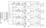
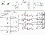
I'm thinking of around 5 pots in the big room being read via ADC by one PICAXE then those values being transmitted serially to a second PICAXE in the electrical closet where the load controllers are located. A multiconductor (5?) cable is in place between the two locations for the original system. Since isolation of the PICAXE system from the load controllers is a good idea I'm thinking PWM out to a LED based opto device/circuit would one way of accomplishing the goal of 0 to 5 VDC to the controllers. Not sure of the current requirements but I would guess it isn't over 1A per load controller.

Does anyone have experience with this sort of thing and/or what are your thoughts on the best way to go about this?
 

hippy

Ex-Staff (retired)
Having worked on microcontroller lighting systems for years I guess I'm your man.

First, check the dimmers do use 5V, and not 10V or even -10V.

Each dimmer channel should include its own opto-isolation so no need to add any yourself; you just need to provide the voltage. The easiest way to do that is use a DAC or PWM to generate a single voltage, then feed that through a multiplexor into ( up to ) 25 sample and hold circuits.

Alternatively you can use DMX512 which will be much easier - Check if the dimmers support that. If not it's a choice of buying a DM512 to 5V ( or 10V ) converter and controlling that, or building your own version of that with a PICAXE controlled by serial as described above.

If the dimmers have a brand name then that would be useful to know. If home built then a circuit would really be a prerequisite.
 

premelec

Senior Member
What Hippy sasys and...

I used a TI 8 channel DAC serially loaded from 08M with success some years ago - units still working -
I used TI TLC5628 8 ch DAC - they also have TLC5620 4 channel DAC unit...
 
Last edited:

hippy

Ex-Staff (retired)
Good solution from premelec with the multi-channel DAC and probably far easier than multiplexed sample and hold.
 

premelec

Senior Member
Tried that... & 14M2 PWMOUT x 4

@Hippy before I settled on the DACs I tried a wide variety of sample and hold etc - they seemed likely to work but were troublesome compared to the DACs with output latched values you could set and forget! However the DAC to current method I was using was not so energy efficient which in my app was not an issue [low power LED stuff]. I noticed that there are 16 channel drivers with PWM out for each channel but they required a very long instruction to change a channel and the 08M didn't seem up to the job, With 4 PWMOUTs on a PICAXE 14M2 I'd suggest using 2 of these as an economic solution too [I've tried the 14M2 running 4 PWMOUTs and it works well...]
 

lewisg

Senior Member
Thanks for the excellent responses! The lighting system is a Lithonia Sequel. It's been a while since I have been on site and since the local rep was supposed to fix it I discarded my notes. The control system is obsolete but there is a interface board that allows interfacing the more modern Synergy system with the load controllers however that is overkill for what they want to do.

Hippy, now you mention it 0-10 is more likely the range.

Premelec, those TI DACs look like the bomb for this! 2X output, 16-DIP and DigiKey has them! Do you have any code to share on the serial interfacing?
 

premelec

Senior Member
Hippy gave me the suggestion for code I used - which was to make up a 12 bit word and shift it out with a bit variable and two wires to the DAC - clock and data. I'll see if I can find some useful code - it wasn't too hard once you looked at the data sheet and saw what the output data needed was. It's possible some of the newer serial commands [than I had with an 08M] would work better - however the bit banging worked fine... note that the resolution will only be 8 bits which may be too coarse for your app - or not.

I'm attaching [I hope!] the basic bones of driving the DAC with 08M
 

Attachments

Last edited:

lewisg

Senior Member
Very cool! Thanks! I think I understand how the code works. It's been a long time since I have done any bit banging like that...

Since the idea is to get the brightness level from a pot using ADC 8 bits was what I was thinking of. I don't know how that will work in the real world. It is considerably finer than the 16 levels in the original versions of X-10, hardly "architectural" though.

Do you make provisions in code to "smooth" the ADC values from a pot? I certainly don't want lights to be jittering up and down. I suppose one way is to regard the pots as presets and have a take button that would initiate a ramp to the new levels. Might be more dignified that way.
 

premelec

Senior Member
There area lot of considerations on that - it may show up as percentage change being the main visual effect - going from ADC 2 to 4 may seem large compared to ADC 20 to 22 - it depends on visual our perception system and other lighting in the area already there - you'll just have to try things out - noise would be your main trouble with the ADC input changing around... and the quality of the pot etc... Note that you can control the reference voltage on the DAC with another DAC section thus getting much finer resolution - or use a 10 or 16 bit DAC. One note on PICAXE PWMOUT controlling an LED is that the first few steps are noticeable but then the transitions aren't obvious [in something I made recently]. Anyhow you are about to find out what works - have fun!
 

lewisg

Senior Member
A VERY NICE person sent me a schematic:
LoadController.jpg

The part posted is 1/4 of a page, from page 20 of the schematics for the system. Lots of Z80 and the like...

It looks like it can use pwm for dimming. I haven't done much of that. Good idea or stick to the DACs?
 

hippy

Ex-Staff (retired)
It looks like it can use pwm for dimming. I haven't done much of that. Good idea or stick to the DACs?
That's for directly switching the mains loads so stick to DAC for creating signals into your existing dimmers.

If you want to build an integrated unit which takes signals from the controller and directly controls the lamps then you're in a whole new ballpark. You'll need to be looking at mains zero-crossover and phase triggering rather than PWM. To get 256 levels of brightness you have to trigger the triacs to a timing resolution of 65us and that's going to be tough going to impossible for a PICAXE controlling more than one channel.
 

lewisg

Senior Member
That's for directly switching the mains loads so stick to DAC for creating signals into your existing dimmers.
What you see in the schematic is the usable part. The 8 lines on the left going into the 2803 darlington come out of a Z80. The other 19.75 pages of schematics are completely digital.


If you want to build an integrated unit which takes signals from the controller and directly controls the lamps then you're in a whole new ballpark. You'll need to be looking at mains zero-crossover and phase triggering rather than PWM. To get 256 levels of brightness you have to trigger the triacs to a timing resolution of 65us and that's going to be tough going to impossible for a PICAXE controlling more than one channel.
Unless I'm completely misunderstanding zero crossing timing a on or off digital pulse to the IL402 optos is where this is headed. Please forgive my ignorance on this, I was just figuring if I sent 0 to 5VDC to the IL402 optos it would "magically" vary the throughput of the MAC15 triacs. Your assistance and further research points out how naive I was...

What I am wondering now is if there is a way to trigger PWM edges using a zero cross pulse. I understand the concept of interrupts but have never used them on a PICAXE or other micro. I'm guessing the best PICAXE solution would be to have one 08M2 (2us resolution at 32MHz?) for each output channel due to timing.

Thanks for all the help!
 

premelec

Senior Member
At one point I was using triacs and incandescent stuff with my DAC setup - the DAC went into an LM324 op amp comparator which fired the individual lamp optoisolator triac phase control - all the comparators went to a sawtooth wave to compare with the DAC input. The sawtooth was generated from mains zero crossing start point. Thus the DAC output controlled where the triacs were turned on - and phased with mains zero crossing. It worked fine with incandescent lamps but seemed not required with LEDs...
 

lewisg

Senior Member
At one point I was using triacs and incandescent stuff with my DAC setup
That sounds very good. I have researched and am having difficulty in figuring out how to accomplish this. I have some LM358 op amps on hand but have only used them to make signals bigger. I'm assuming I would build a zero crossing detector (optocouplers seem popular) and feed it into one of the op amp inputs while the DAC would be configured as a voltage divider to feed the other op amp input. As to how to figure all the resistor values and the best way to configure the circuit I'm a little lost.

On hand I have:
TLC5628 DACs
LM358 op amps
IL5, 6N136 and 2501 optocouplers

I have looked at the following ZC circuits:
www.dextrel.net/diyzerocrosser.htm
www.dainst.com/info/circuits/zero_crossing.html
www.avrprojects.info/files/images/Dimmer-Schmatic.gif (left half to pin 4 on the Atmega)

Any thoughts, diagrams, schematics or other help would be appreciated.
 

premelec

Senior Member
I too am lost... what loads - type and current and voltage - are you trying to control? The original topic was simply generating 0-5 volts to feed to some [existing?] lighting controller... When you use an op amp as a comparator you simply put one signal on + in and other one on - in and it then drives to saturation either on or off output [with various offsets depending on amp used] - and in my case the op amp output went to an optocoupler driving a triac - I haven't looked at your URLs ref'd above as I am not clear what you are trying to do... Do you have something you are trying to control with 0-5volts?
 

lewisg

Senior Member
I thought I was trying to control an existing lighting system with 0-5V. However that was because I was given some bad information.

Here is the schematic from post 10:
LoadController.jpg
What you see is the actual power components in one power module. There are 2 cabinets that contain 9 of these power modules. Each module can control 4 loads, either with triac dimming or by relay. Off the left of the schematic is a Z80 and 19.75 previous pages of 1990's digital electronics. What my (possibly foolish) notion is to replace all that broken and outdated stuff with something simpler. They never needed 16 channels of control or a bunch of presets. As I stated in the original post I'm looking to have around 5 channels of control for the 24 or so lighting loads. I believe them all to be incandescent however if some are not then use the relay option for on/off control.

Since my original post I have learned a lot thanks to the excellent responses here. I now have some understanding of how triac switching works and realize that I need to either turn on or turn off the load via triac at zero crossing and do the opposite some number of microseconds later. For example if the load is turned on at ZC then turned off 60us later it will be around 1/2 brightness. If instead you go the other way around an turn the load on 60us after ZC and turn off at the next ZC you will have approximately the same 1/2 brightness.

So how to accomplish this?

In this example avrprojects. A ZC signal is fed directly into a Atmega which then controls the timing of the triac. As Hippy pointed out a PICAXE could likely only control one output channel due to timing issues. My notion is 08M2s are cheap so there is one for each of the 5 control channels. My math indicates a 08M2 running at 32MHz should be capable of 2us resolution. This should give around 60 brightness levels.

Premelec seems to suggest that using a DAC, ZC circuit and comparator circuit could offload this timing from the PICAXE. My understanding of post #13 above was that you had done this. It sounds possible that some sort of RC circuit fed from the DAC could keep the LED in an optocoupler on for some number of microseconds after a ZC trigger. Possibly I'm all wet.

In any case this is a backup plan. Since I now have a complete set of schematics it is possible that the digital part of this lighting system can be fixed. Could be something as simple as the 75176 RS485 chips that are on just about every board. However since the authorized reps have been over this system without providing a fix...
 

hippy

Ex-Staff (retired)
What my (possibly foolish) notion is to replace all that broken and outdated stuff with something simpler.
Okay; it seems we have gone from producing something which can feed existing dimmer circuits to replacing the existing dimmer circuits.

As Hippy pointed out a PICAXE could likely only control one output channel due to timing issues. My notion is 08M2s are cheap so there is one for each of the 5 control channels. My math indicates a 08M2 running at 32MHz should be capable of 2us resolution. This should give around 60 brightness levels.
I think you are underestimating the difficulty of what you are trying to achieve using pure digital control and overestimating the PICAXE's ability to achieve it. I'm not sure of the basis of your maths but at 60Hz, and 60 steps you will need to trigger triacs with an accuracy of about 140us - I forgot you have to trigger on each half phase in earlier calculations; for 256 steps you need 32us timing resolution.

One problem is with light levels not being perceived as linear and with only 60 steps you may not have enough steps at low brightness to set the lighting as finely as you may want.

I'm particularly intrigued as to what algorithm you will be using to trigger the triacs from the raw input signals, particularly that all cases have to be catered for; where each channel level is different, where each channel level is the same and where each channel level is one step higher than the previous or next. You need to ensure that each channel is switched exactly when required, and that may be simultaneously with other channels. If you delay channels then they will have different brightness levels even though intended to be at the same level and light levels of channels can change when it shouldn't if a different channel is altered.

At the very least this will be 'a challenge'. I'd go for one PICAXE per channel simply to keep it simple but perhaps it is possible to do more per 08M2 - Three or four channels would be the physical limit and I wouldn't want to share Pin 0 / serial Out with triac control, and that doesn't take into account how you are going to get any input into the 08M2 to control outputs.

If using analogue inputs we're back to either sending multi-wire analogue signals from the controller or having a means of converting serial to 0-5V signals to control the PICAXE dimmers. Using serial into the dimmer controllers will present similar problems to servo-jitter and unsolicited serial input with lighting channels potentially flickering like crazy. It's possible to have the dimmers synchronise the controller to the dimmer's zero-crossover to minimise that but it's another level of complexity. If the controller delivers multi-wire analogue to the existing dimmers then you'll have to do none of that if you keep with what exists, only replace the dimmer electronics.

I would suggest grabbing a 20X2 ( and another PICAXE to generate mains-crossover pulses every 100Hz/120Hz ), write the code for a two channel analogue input dimmer and see how that goes using a logic analyser / scope to verify the working of that. Then expand the code to see how many channels you can control without unacceptable output jitter.
 

hippy

Ex-Staff (retired)
Proof of concept code for an 08M2-based two channel analogue dimmer. Completely untested and needs tweaking.

Don't put it anywhere near a live system until it's been tweaked and tested using logic analyser / scope and LED's and you are sure of what you are doing.

The hard part is in juggling which triac to fire first, calculating the time to firing and the time to firing the second. The longer it takes to do that ( if there were more channels ) affects the maximum brightness put out, and also dictates how long the crossover pulse must be.

The 'time2nd' doesn't take into account how much execution overhead there is so would need tweaking, as does the 'K' multiplier to adjust the minimum and maximum times to fire. Running at a higher speed will reduce jitter but then complicates the timing, complicates the calculations.

Code:
#Picaxe 08M2

Symbol XOVER   = pin3      ' Pin 3 is mains crossover input +Ve pulse
Symbol ADC_1   = 2         ' Pin 2 is channel 1 ADC input
Symbol ADC_2   = 4         ' Pin 4 is channel 2 ADC input
Symbol TRIAC_1 = %00000001 ' Pin 0 is channel 1 triac output
Symbol TRIAC_2 = %00000010 ' Pin 1 is channel 2 triac output

Symbol time1st = w0 ' b1:b0
Symbol time2nd = w1 ' b3:b2
Symbol fire1st = b3
Symbol fire2nd = b4
Symbol level1  = b5
Symbol level2  = b6

Symbol K       = 100

dirs = TRIAC_1 | TRIAC_2

Do : Loop Until XOVER = 0

Do

  Do : Loop While XOVER = 0

  pins = %00000000

  ReadAdc ADC_1, level1 : level1 = level1 ^ $FF
  ReadAdc ADC_2, level2 : level2 = level2 ^ $FF

  ' For testing
    level1 = 0
    level2 = 255

  If level1 = level2 Then
    time1st = level1 * K
    fire1st = TRIAC_1 | TRIAC_2
    time2nd = 0
    fire2nd = TRIAC_1 | TRIAC_2
  Else
    If level1 < level2 Then
      time1st = level1 * K
      fire1st = TRIAC_1
      time2nd = level2 - level1 * K
      fire2nd = TRIAC_1 | TRIAC_2
    Else
      time1st = level2 * K
      fire1st = TRIAC_2
      time2nd = level1 - level2 * K
      fire2nd = TRIAC_1 | TRIAC_2
    End If
  End If
  
  Do : Loop While XOVER = 1

  PauseUs time1st
  pins = fire1st

  PauseUs time2nd
  pins = fire2nd

Loop
 
Last edited:

premelec

Senior Member
FWIW schematic 4Ch phase control

Dim0_10.jpg A schematic from about 9 years ago similar to what I controlled with 08M and DAC...
 

lewisg

Senior Member
Thanks! Both of you have fed my brain this morning.

@Hippy I'm assuming the zero cross waveform your code is expecting is a square wave with transitions at ZC. The code runs as expected in the simulator but I need to get a ZC circuit up before testing with a chip. Please don't worry about me and "real" voltages. I'm well experienced with that sort of thing and will test safely, first at low voltages with a scope, before even attempting to use triacs at line voltage.

As far as light levels are concerned, this isn't theatrical or even architectural quality that is being aimed for. Think more along the lines of set the lights and leave them at those levels. A "take" button should solve ADC jitter. Currently they are getting along with going to the basement to turn the lights on and off. I'm aiming for better than that for less than a tenth of what replacing the broken control system would cost. Currently other financial obligations have precedence over lighting for these folks. If cost wasn't an overriding issue I'd figure out some way to convert the whole thing to DMX.

@Premelec Cool circuit! I wish I had more experience with op amps since they are one of the best little building blocks around. I will need to get a few more parts in before I can try this out.

Both methods are wonderful!
 

hippy

Ex-Staff (retired)
@Hippy I'm assuming the zero cross waveform your code is expecting is a square wave with transitions at ZC.
A positive going pulse around ( before, during and after ) the crossover. That's usually achieved by bridge rectifying the secondary of a mains transformer and feeding into a transistor. Or something similar.

As the crossover approaches the pulse goes high, the triac drives are turned off ready for the triacs to stop conducting as crossover occurs, the ADC's are read and any calculations are done, when the crossover passes, the pulse goes low and timing is done from that point.
 

premelec

Senior Member
Looking at the schematic of existing control I think you could keep the MAC15A10s and couplers and simply drive them with a new driver - could be DAC and comparators - the only 'tricky' part is getting the sawtooth synced with mains ZCs and stable. Keeping phasing OK with multiple different trigger points for many triacs gets into some timing difficulty. In some instances offsetting triggering is desirable - so all lights don't go on at once with attendant current pulse on mains.

One thing to consider about op amps is that they "try" to keep in + to in - at 0 volts in operation - in short any voltage between the inputs will drive the output all the way high or low - hence linear amplifying circuits and such use corrective [negative] feedback. When used as comparator you don't need the output att anything but high or low. Read the data sheets in regard to common mode rejection & range and max/min voltages etc. . Common mode means the voltage above common at the inputs... In short the amplifier responds to the difference of the + & - inputs over a certain range of voltages above common.
 
Top