OT: Singing inductors in SMPSs

MartinM57

Moderator
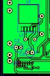
I've just been making some boards up with my favourite SM regulator (LM2575-5.0), circuit exactly as data sheet(*), and the power supply works fine.

At low currents the power supply components are silent - at higher currents (220mA or so, so well inside specs) the wire wound inductors start to mechanically "sing" at a high frequency (no, don't know how high - I'd guess a few Khz).

I tried putting some threadlock into the coils of the inductors and letting it dry - it might have made a marginal difference but hardly noticeable to be honest.

They're a respectable make from from Farnell (http://uk.farnell.com/jsp/search/productdetail.jsp?SKU=1864386 - the datasheet is correct but the picture and legend is not as they are 2 pin devices (I told Farnell ages ago but they haven't corrected it yet))

Ideas from the collective? It's not loud, but you can definitely hear it and it's a right PITA :(

(*)fractionally marginal - maybe I should be using 470uH from Fig 4 of the data sheet, but I wouldn't have thought it would make much/any difference.
 

fernando_g

Senior Member
The LM2575 has a fixed 52 Khz oscillator. A human ear cannot hear that frequency. So this is not it.

Most likely, you are experiencing subharmonic oscillation (due to an unstable loop) or pulse skipping.

Time to bring out the o'scope and post some waveforms
 

MartinM57

Moderator
Yep I can do that (I hadn't scoped it - was getting a bit late - easier to ask the collective :D) - the day job is in the way today, so will do tonight...
 

MartinM57

Moderator
PCB layout (bottom copper) attached - diode is on top side on the two right hand pads - short traces before D asks ;)
Capture.JPG
...note the Tag-Connect connector at the bottom. Would have been nice if I'd have got the pins in the right order :(
 

Dippy

Moderator
It might just be because you picked the cheapest inductor on the planet ?? :)

I haven't got the time to study data sheets right now but often the construction as well as value can do things.

I did two 240VAC to 3v3DC buck designs a while back. Same circuit. Different layout and inductor style and subtly different AC/DC values. One sang the other was quiet.
No nasty measurable harmonics in either.

It could simply be Inductor construction/core/style. They do have an effect in switcher circuits. Maybe DC resistance too high? Diode type/spec good? (And not the cheapest?).

I've never used that milled PCB method so I can't comment on that aspect.
 

MartinM57

Moderator
I do tend to sort by price ascending in the Farnell parametric results :)

Diode is as per datasheet - 1n5158

It's a proper gerber-based etched/masked/silk-screened HASL production quality PCB - I posted a cheap .jpg screen dump of the Diptrace layout.

I'll fire up the Tek tonight...
 

John West

Senior Member
The turns may not be wound tightly enough in your batch of coils. I would suggest potting the coils in something much more firm than threadlock, such as epoxy resin.

As for the photo:
Image is for illustrative purposes only.
Please refer to product description


The supplier can't reasonably post pics of every one of the myriad devices they stock, so they (and many others) just paste up a generic photo of a device of the general type being sold, then post the disclaimer below it.
 
Last edited:

Dippy

Moderator
Haha. Now THAT would be an irony - saving 50p on the inductor and having to spend an extra £1 on the glue.... :)
 

MartinM57

Moderator
Weird...

Top trace = pin 1 (input)
Middle trace = pin 2 (called the output pin, but at the junction of the diode and inductor)
Bottom trace = pin 4 (called the feedback pin, but the actual output (Vcc) voltage)

The middle trace isn't much like the nice square wave in the photo in the data sheet

tek00000.pngswitch.JPG
 

john2051

New Member
Hi, reading your woes takes me back to the first dual standard tvs I worked on. The lopts used to ring at 16.625KHz, which was their self resonant frequency. Could that be or some harmonic mixing you are hearing?
One reason why early lopts were covered in bitumen. I think they still are, but also encased in plastic. Fortunately for me now, the max frequency I can hear is about 12KHz!!
There has to be a reason, could you try damping it with a resistor?

Regards john
 

John West

Senior Member
That ugly waveform feeding the inductor is the key. If you picture the waveform shown as it would look after being filtered through a lowpass filter, you'd see that it has a strong oscillating frequency component of around 5 kHz or so. Almost any inductor would "sing" with such a nasty input.

I suspect when you are operating below the load point where the "singing" starts the inductor's input looks much better. But you don't mention the load current you are showing the waveform for so I'm just guessing.

Unless you have some bad inductors and the cores are saturating I'd suggest the problem lies in the filter capacitors. You never actually specified their values, types, or ESR specs. You just said you were following the datasheet info. Are you?

The ESR value is critical and must be neither too high nor too low. What caps are you using? What are their specs? In switchers, it matters.
 
Last edited:

Dippy

Moderator
In addition to above..... check your schematic and artwork.
Is this just the simple example buck?

Unless I'm going daft your diode is in the wrong place.
You seem to have it going from ground to f/b.
It should be going Ground ---->|--- Output pin.

...unless all the artwork is reversed, in which case... start again. :)
 
Last edited:

MartinM57

Moderator
Some answers, but I'm not at home until tomorrow night so will follow up tomorrow:
- circuit/layout is fine - I forgot to clearly say that the components are on the bottom side (I did say you were looking at the bottom copper :)) - so pin 1 of the regulator is on the right as you look at the .jpg
- yes, just the simple circuit from the datasheet
- load is about constant 220mA resistive
- ESR of caps - don't know - will check out
 

Dippy

Moderator
Aha, then I AM going daft.

Sadly, I'm going even dafter...
(though I have to say that the track from Output to L1 is a bit long and weedy.:) )
I see the downstream side of L1 goes to LM2575 feedback, but then where?
Cout+ should be almost sitting on that junction.

Comments.
LM2575-Output --- D1k --- L1 (o/p end) should ideally be tighter.
In fact, LMO/P could be direct to L1 and bring LMsupply+ in from side.
L1 (downstream) -- Cout+ pad should be almost touching. But , other than to FB, I can't see where it goes ... ??


LMout --D1k--Cout+ should be very tight together.

Personally, I like big butch grounds, I'm not a great fan of the plane tiddlers to the diode ground end pad.
I know it's easier to solder.
Tip: S/mount diodes give better results ; more intimate Matron!


Cin and Cout should be low ESR, Cout should be greater than R05 ohms.
Probably irrel, but I wouldn't have magnetics going over other tracks - in this case +Vin.

Good luck with it Martin. A good fiddle usually sorts things out.
 

MartinM57

Moderator
I can't check as I'm not at home, but I suspect the layout will become clear (and correct) when you see the top copper :)
 

Dippy

Moderator
Oh Martin ... you mean after 2412 postings you've left some crucial info out? :rolleyes:

Anyway, I still stand by my comments about track lengths and component proximity.... but then, I reckon you knew I was going to say that.

I'll leave you to it then. Just remember, after spending £3k on a 'scope an extra 20p on components shouldn't be a prob :)
 

fernando_g

Senior Member
Top trace = pin 1 (input)
Middle trace = pin 2 (called the output pin, but at the junction of the diode and inductor)
Bottom trace = pin 4 (called the feedback pin, but the actual output (Vcc) voltage)

The middle trace isn't much like the nice square wave in the photo in the data sheet

View attachment 8826View attachment 8827
Hmmm.
The loop is clearly unstable.
However, this regulator has internal frequency compensation, so traditional loop unstability may not be the root cause.

Could it be, among other things already mentioned by other posters, that the inductor is saturating?

These "simple switcher" family of devices are usually guaranteed to work properly only with components for which National has fully characterized as a system.
 

MartinM57

Moderator
PCB is fine - there is a top copper trace connecting downstream side of L1 to the output capacitor and Vcc...don't ask me why it's on the top as it doesn't need to be.

Changed the marginal 330uH 0.4A inductor to a 470uH 0.7A inductor - no change
Changed the 1N5818 to a 11DQ06 - no change

Changed the load to a pure resistance - initially to take 220mA and then to take 330mA - complete silence at all load values :(

So it's something to do with the load - a few MAX7219-alikes and LEDs - all decoupled as their datasheets as well, which make the inductors sing at only 130mA.

I shall keep fiddling...
 

john2051

New Member
Hi, sorry I was a bit vague with 'lopts', giving away my age!! I am curious why you are still having problems.
Could it be material type, or saturation of the core?
Good luck
Regards john
 

premelec

Senior Member
@Martin... if you changed the inductor and it's still singing what makes you think it's the inductor making the noise? Also have you tried a toroid inductor which has greatly reduced external field... note that some ceramic capacitors have piezo effects and might sing... and finally have you considered singing along and enjoying the choir? :)
 

MartinM57

Moderator
It's definitely the inductor - place a small metal jewellers screwdriver on it and the sound is amplified so that it can be heard across the room.

I can draw 330mA with a resistive load and it's totally silent - 160mA load from the 7219s/LEDs and it sings like no-ones business.
 

Dippy

Moderator
Well, I shan't mention Cout track lengths any more ... so, have you decoupled/bypassed 7219 supply?
"connect a 10µF electrolytic and a 0.1µF ceramic capacitor between V+ and GND as close to the device as possible."

That chip has some switching so maybe there is a nasty resonance caused.
 

inglewoodpete

Senior Member
I think it's time to determine why it is singing at low loads. Have you inserted a low value resistor in series with the offending inductor and 'scoped the current? Any funny shapes?

As many have noted, there are so many one-liners that come to mind..... Why is it singing? If it didn't know the words, it would just hum.
 

MartinM57

Moderator
Yes and yes (to the decoupling/bypassing of course :D, and adding more in parallel (via extra caps, rather than bigger ones, and all sorts of values, makes zero difference)...but that my attention is now pointing to the load. More fiddling required...
 
Last edited:

John West

Senior Member
A bit more information comes out, I see.

When you say you change the load to a pure resistive load you are implying that the load you are trying to drive with these switchers is not a resistive load. What is it?

Loads that can sharply and rapidly fluctuate, (inductive or capacitive, certain types of lamps, etc) can often induce oscillations into simple switchmode supply circuits. They just aren't always capable of controlling such loads, and need help.

If you are driving a resistive load perfectly quietly, then there's nothing wrong with the inductor in the switcher.

If you are driving an inductive load in particular you likely need better load filtration. The switcher may well be attempting to drive a load that it cannot, one that "talks back to it," and that is throwing it into the odd control oscillation that we see in your driving waveform. The switcher is attempting to track the load fluctuation but can't keep up.

At this point I will say again that I don't see the switcher's inductor as being the problem. Especially as you say it's dead quiet into a resistive load.

So we're back to what your load actually is, and proper filtration on the load to keep it stable and quiet down the switcher so it too is stable.
 
Last edited:

MartinM57

Moderator
@IWP - Lots of funny shapes at the D1/L1 connection - with a resistive load it's absolutely exactly as the analogue screen from the datasheet (and post #9).

At zero load, every falling edge gets half way down and oscillates like crazy in a reducing amplitude sine wave until it meets the next rising edge - screen shot later...

I'm sure it's the load - the tune changes slightly as the digits change - but why it has such a big effect on the power supply is yet to be determined
 

MartinM57

Moderator
The load is a separate plug in board (so it was easy to remove and just bridge Vsupply and Gnd with low value 2W resistors to model a pure resistive load):
- 2 x AS1107 (MAX7219 clones), each with a 10uF SMD elctrolytic and a 0.1uF X7R SMD, plus a 10K SMD Rset
- 12 x single digit 7 segment LEDs
- 1 x 4 digit 7 segment LED

(plus the other components on the same board as the SMPS - a microcontroller, an opamp, an RTC, some FRAM, a voltage reference and about 35 passives - all very light stuff, and running when the resistive load is drawing 330mA and all is quiet)

Sorry, no pictures available....
 
Last edited:

John West

Senior Member
Try a 1000uF electrolytic cap on the output of the switcher. As I said earlier, I think something is fluctuating in the load more quickly that the switcher can smoothly respond to. I don't know what, but a larger capacitance might slow things down enough for the switcher to keep up.

If the cap alone doesn't do the trick, then instead put about a 20uH choke in series with the load and on the load side of it place about a 100 uFd cap to ground. The inductor helps block spike type transitions while the capacitor slows down overall load changes, making the load look more stable to the switcher.
 
Last edited:

MartinM57

Moderator
Additional capacitors across the board supply pins - no real difference whatever value

100uH in series with the board Vsupply - singing is lessened, but still very annoying
330uH in series with the board Vsupply - singing is lessened even more, but still annoying
3 x 330uH (all I had to hand) in series with the board Vsupply - very encouraging, singing still just audible
3 x 330uH in series with the board Vsupply plus 330uF to ground on board - silence. (well maybe the inductor is singing Silence is Golden, but I can't hear it)

So nothing fundamentally wrong with the LM2575 circuit, but it doesn't like the LED drivers and LED circuit being attached. A bit disappointing, but a lesson for the future. Maybe there are other better SM regulators?

So a qualified success at the moment - just need to find room for the components on (yet) another board revision - and another 40p in component costs.

Thanks to all (no names, I might miss some out) - lots of good advice on this thread...the PICAXE collective has come good (again)
 

John West

Senior Member
You can reduce both the value of the filter inductor and the load-side capacitor while observing the switcher output waveform to determine at what point it becomes unstable again. Then purchase filter components a safe size larger, but still cheaper than those you started with that stopped the singing.

As long as the switcher chip's drive voltage to the inductor looks stable, I'm sure there will be no singing going on, audible or otherwise.
 

marks

Senior Member
I think your current value of your inductor is far to low for 330uH should be 1 amp this should give youa cleaner supply
 
Top